Posts by Align Manufacturing
What is 440C Stainless Steel? Properties & Knife Applications

Introduction
440C stainless steel is one of the most widely used materials in knife manufacturing, prized for its exceptional combination of hardness, corrosion resistance, and edge retention. This comprehensive guide explores the properties, applications, and characteristics that make 440C a preferred choice for knife makers and manufacturers worldwide [^1^].
Understanding 440C stainless steel is essential for anyone involved in blade production, from hobbyist knife makers to industrial manufacturers. This martensitic stainless steel offers a unique balance of performance characteristics that have made it a staple in the cutlery industry for decades [^2^].
What is 440C Stainless Steel?
440C is a high-carbon martensitic stainless steel that belongs to the 440 series of stainless steels. It is known for its high hardness and excellent wear resistance, making it particularly suitable for applications requiring sharp edges and durability [^3^].
Chemical Composition
The chemical composition of 440C stainless steel includes:
- Carbon (C): 0.95–1.20% – Provides hardness and edge retention
- Chromium (Cr): 16.0–18.0% – Offers corrosion resistance
- Manganese (Mn): 1.0% max – Improves hardenability
- Silicon (Si): 1.0% max – Enhances strength
- Molybdenum (Mo): 0.75% max – Increases wear resistance
- Phosphorus (P): 0.04% max
- Sulfur (S): 0.03% max
This composition gives 440C its characteristic properties that make it ideal for knife applications [^4^].
Key Properties of 440C Stainless Steel

Hardness and Heat Treatment
440C stainless steel can achieve high hardness levels through proper heat treatment:
- Annealed Hardness: 200–250 HB (Brinell)
- Hardened Hardness: 58–60 HRC (Rockwell C)
- Maximum Hardness: Up to 60 HRC with optimal heat treatment
The heat treatment process involves:
- Austenitizing: Heating to 1850-1900°F (1010-1038°C)
- Quenching: Rapid cooling in oil or air
- Tempering: Reheating to 300-800°F (149-427°C) to achieve desired hardness [^5^]
Corrosion Resistance
440C offers excellent corrosion resistance due to its high chromium content (16-18%). This makes it suitable for:
- Kitchen knives exposed to moisture
- Marine applications
- Food processing equipment
- Medical instruments [^6^]
Wear Resistance
The high carbon content and presence of chromium carbides provide exceptional wear resistance, ensuring:
- Long-lasting sharp edges
- Reduced need for frequent sharpening
- Durability in cutting applications [^7^]
Machinability
440C stainless steel has moderate machinability in the annealed condition. However, it becomes more difficult to machine after hardening. Manufacturers should consider:
- Using sharp cutting tools
- Maintaining proper cutting speeds
- Applying adequate coolant
- Allowing for tool wear [^8^]
Applications of 440C Stainless Steel

Knife Manufacturing
440C is extensively used in various types of knives:
Kitchen Knives
- Chef’s knives
- Paring knives
- Utility knives
- Boning knives
Sporting Knives
- Hunting knives
- Fishing knives
- Pocket knives
- Tactical knives
Industrial Blades
- Cutting tools
- Surgical instruments
- Razor blades
- Precision cutting equipment [^9^]
Other Applications
Beyond knives, 440C is used in:
- Ball bearings and races
- Valve components
- Nozzles
- Mold and die components
- Measuring instruments [^10^]
440C vs Other Knife Steels
440C vs D2 Steel
| Property | 440C | D2 |
|---|---|---|
| Hardness | 58-60 HRC | 55-62 HRC |
| Corrosion Resistance | Excellent | Good |
| Edge Retention | Good | Excellent |
| Ease of Sharpening | Moderate | Difficult |
| Price | Moderate | Higher |
440C vs 154CM
| Property | 440C | 154CM |
|---|---|---|
| Hardness | 58-60 HRC | 58-61 HRC |
| Corrosion Resistance | Excellent | Excellent |
| Toughness | Moderate | Better |
| Price | Lower | Higher |
440C vs VG-10
| Property | 440C | VG-10 |
|---|---|---|
| Hardness | 58-60 HRC | 60-62 HRC |
| Corrosion Resistance | Excellent | Excellent |
| Edge Retention | Good | Excellent |
| Origin | American | Japanese |
Advantages of 440C Stainless Steel
- Excellent Corrosion Resistance: High chromium content provides superior rust resistance
- High Hardness: Achieves 58-60 HRC for excellent edge retention
- Good Wear Resistance: Carbide content ensures long-lasting performance
- Cost-Effective: Offers good performance at a reasonable price point
- Proven Track Record: Decades of successful use in knife manufacturing
- Availability: Widely available from multiple suppliers
- Heat Treatable: Can be optimized for specific applications [^11^]
Disadvantages and Limitations
- Moderate Toughness: Can be brittle compared to some modern steels
- Machining Difficulty: Requires specialized equipment after hardening
- Edge Stability: May chip under heavy impact compared to tougher steels
- Not Premium Grade: Outperformed by newer super steels in some applications [^12^]
Manufacturing Considerations
Forging
440C can be forged at temperatures between 1700-2100°F (927-1149°C). Proper forging requires:
- Uniform heating
- Adequate reduction ratios
- Controlled cooling to prevent cracking [^13^]
Heat Treatment Best Practices
- Preheat to 1200-1400°F (649-760°C) before austenitizing
- Austenitize at 1850-1900°F (1010-1038°C) for 30-40 minutes
- Quench rapidly in oil or use air quenching for thinner sections
- Temper immediately at desired temperature (typically 300-400°F for knives)
- Cryogenic treatment optional for maximum hardness [^14^]
Surface Finishing
440C accepts various surface finishes:
- Satin finish: Brushed appearance, hides scratches
- Mirror polish: High reflectivity, maximum corrosion resistance
- Bead blast: Matte finish, uniform appearance
- Acid etch: Patterned finish, enhances aesthetics [^15^]
Quality Control and Testing
Hardness Testing
Rockwell C (HRC) testing is the standard method for verifying heat treatment:
- Test multiple points on the blade
- Ensure consistency across the piece
- Document results for quality assurance [^16^]
Corrosion Testing
Salt spray testing (ASTM B117) can verify corrosion resistance:
- 24-48 hour exposure
- Visual inspection for rust formation
- Comparison to industry standards [^17^]
Conclusion
440C stainless steel remains a dependable and cost-effective material for knife manufacturing because it offers a strong balance of hardness, corrosion resistance, wear resistance, and edge retention. Even as newer premium alloys continue to enter the market, 440C still holds its place as a practical option for many blade applications thanks to its proven performance, broad availability, and reasonable cost. For manufacturers and buyers looking for a steel that performs reliably across kitchen, sporting, and industrial uses, 440C continues to be a smart and versatile choice.
At Align Mfg, we understand that material selection is never just about technical properties on paper. It is about choosing the right process and alloy for the end-use environment, performance target, and production requirements. Whether your project involves precision-machined components, blade-related parts, or broader metal manufacturing solutions such as sand casting stainless steel, our team focuses on helping customers turn material knowledge into real-world manufacturing results with the right balance of quality, consistency, and cost efficiency.
FAQ
Q: Is 440C good for kitchen knives?
A: Yes, 440C is excellent for kitchen knives due to its high corrosion resistance and ability to maintain a sharp edge. It’s particularly suitable for knives that will be exposed to moisture.
Q: How hard can 440C stainless steel get?
A: With proper heat treatment, 440C can achieve hardness levels of 58-60 HRC, with some applications reaching up to 60-61 HRC.
Q: Is 440C easy to sharpen?
A: 440C has moderate sharpenability. It’s harder to sharpen than softer steels but easier than many modern super steels. Standard sharpening stones work well.
Q: How does 440C compare to 440A and 440B?
A: 440C has the highest carbon content (0.95-1.20%) compared to 440A (0.65-0.75%) and 440B (0.75-0.95%), making it the hardest and most wear-resistant of the three.
Q: Can 440C rust?
A: While 440C has excellent corrosion resistance, it can still rust if exposed to harsh conditions or not properly maintained. Regular cleaning and drying are recommended.
Q: What is the best heat treatment for 440C knife blades?
A: Austenitize at 1850-1900°F, oil quench, and temper at 300-400°F for optimal combination of hardness and toughness for knife applications.
Q: Is 440C suitable for beginner knife makers?
A: Yes, 440C is a good choice for beginners due to its forgiving heat treatment window and widespread availability. However, proper heat treatment equipment is necessary.
Q: How does 440C perform in saltwater environments?
A: 440C performs well in saltwater due to its high chromium content, but regular maintenance (rinsing and drying) is still necessary to prevent corrosion.
Q: What is the typical price range for 440C steel?
A: 440C is considered a mid-range steel, typically costing less than premium steels like S30V or 154CM while offering good performance for the price.
Q: Can 440C be used for Damascus steel?
A: Yes, 440C can be used in Damascus patterns, though it’s more commonly used as a solid blade material. It pairs well with 1095 or 15N20 for contrast.
Q: What grinding methods work best for 440C?
A: Belt grinding with ceramic or zirconia belts works well. For hand sanding, use progressive grits from 120 to 600+ for a fine finish.
Q: How long does a 440C knife edge last?
A: Edge retention depends on use, but 440C typically holds an edge well for moderate use. Heavy cutting may require sharpening after several hours of use.
Q: Is 440C magnetic?
A: Yes, 440C is magnetic in both annealed and hardened conditions due to its martensitic structure.
Q: Can 440C be welded?
A: Welding is possible but challenging due to hardening and potential cracking. Preheating and post-weld heat treatment are essential.
Q: What safety precautions are needed when working with 440C?
A: Standard metalworking safety applies: eye protection, dust masks when grinding, proper ventilation, and heat-resistant gloves during heat treatment.
Partial vs Full First Article Inspection: Complete Decision Guide for Aerospace Suppliers
First article inspection (FAI) requirements confuse even experienced aerospace suppliers. When do you need a full FAI versus a partial FAI? What triggers each type? How do you satisfy different customer requirements from Boeing, Airbus, and other OEMs?
This guide provides clear answers. You will learn the exact triggers for partial and full first article inspections, understand the documentation requirements for each, and discover how to align your FAI process with customer expectations. Whether you are a quality manager, program manager, or supplier quality engineer, this resource eliminates the confusion surrounding FAI requirements.
What Is First Article Inspection and Why It Matters
First article inspection verifies that manufacturing processes can produce conforming parts. Before full production begins, suppliers inspect and document all characteristics of a representative part. This process catches errors early, prevents costly rework, and demonstrates compliance to aerospace quality standards.
The AS9102 standard governs FAI in aerospace manufacturing. This standard defines three types of first article inspection: full FAI, partial FAI, and delta FAI. Each serves a specific purpose and applies under different circumstances.
Understanding these distinctions protects your business. Submitting the wrong FAI type delays approvals, strains customer relationships, and risks production shutdowns. Conversely, performing unnecessary full FAIs wastes resources and extends lead times unnecessarily.
Full First Article Inspection: Complete Verification
A full first article inspection examines every design characteristic on every drawing, specification, and purchase order requirement. This comprehensive verification applies to new parts, new suppliers, or significant process changes.
When Full FAI Is Required
Full FAIs are mandatory in these situations:
- New part introduction – First production of a part number never manufactured at your facility
- New supplier – First delivery from a new subcontractor or material source
- Process change – Manufacturing location, method, or tooling changes that affect form, fit, or function
- Design revision – Engineering changes affecting dimensions, materials, or performance
- Production lapse – Manufacturing interruption exceeding 24 months
Full FAI Documentation Requirements
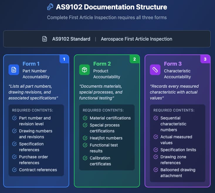
Full first article inspection requires complete AS9102 documentation:
| Form | Purpose | Content |
| Form 1 | Part Number Accountability | Lists part numbers, drawing revisions, and associated specifications |
| Form 2 | Product Accountability | Documents materials, special processes, and functional testing |
| Form 3 | Characteristic Accountability | Records every measured characteristic with actual values |
Each characteristic requires actual measurement against specification limits. Design characteristics include dimensions, tolerances, notes, and surface finish requirements. Special processes require certification from approved suppliers.
Partial First Article Inspection: Selective Verification
A partial first article inspection examines only characteristics affected by a change. This streamlined approach applies when previous full FAIs exist and only specific aspects of the part have changed.
When Partial FAI Is Allowed
Partial FAIs are appropriate when:
- Engineering changes affect limited characteristics (not form, fit, or function)
- Tooling modifications change specific dimensions without affecting overall design
- Process adjustments improve capability on select features
- Material lot changes from qualified suppliers with established traceability
- Minor drawing clarifications that do not change requirements

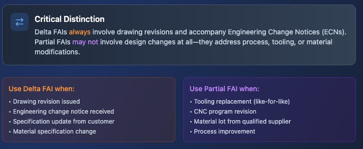
Delta FAI vs Partial FAI: Critical Distinctions
Many suppliers confuse delta FAI with partial FAI. While both involve limited inspection scope, they serve different purposes and apply in different scenarios.
Delta FAI Definition
A delta FAI verifies only characteristics affected by an engineering change. The term “delta” refers to the difference between design revisions. Delta FAIs accompany engineering change notices (ECNs) and demonstrate that modified characteristics meet new requirements.
Partial FAI Definition
A partial FAI verifies characteristics affected by any change and not just engineering changes. This includes process changes, tooling changes, or material changes that do not involve design revisions.
Comparison Table: Delta FAI vs Partial FAI
| Factor | Delta FAI | Partial FAI |
| Trigger | Engineering change (ECN) | Any change (process, tooling, material) |
| Scope | Changed characteristics only | Affected characteristics only |
| Form 1 | Updated with new revision | Updated with change reference |
| Form 2 | Revised special processes if changed | Updated processes/materials |
| Form 3 | Only changed characteristics | Only affected characteristics |
| Customer notification | Always required | Often required |
Understanding this distinction prevents documentation errors and customer rejections.
FAI Trigger Events: Complete Catalog
Knowing what triggers each FAI type prevents compliance gaps. This catalog covers common aerospace manufacturing scenarios.
Design-Related Triggers
| Event | FAI Type | Notes |
| New part number | Full FAI | First production at your facility |
| Drawing revision | Delta FAI | If previous FAI exists; Full FAI if not |
| Specification change | Delta FAI | Affects Form 2 and possibly Form 3 |
| Material specification update | Delta FAI | Requires new material certification |
| Surface treatment change | Delta FAI | New special process approval needed |
Process-Related Triggers
| Event | FAI Type | Notes |
| New manufacturing location | Full FAI | Even for existing part numbers |
| Equipment replacement (like-for-like) | Partial FAI | If capability maintained |
| Equipment replacement (different type) | Full FAI | New process capability required |
| Tooling replacement (worn/damaged) | Partial FAI | Verify affected dimensions only |
| Tooling redesign | Partial FAI | Verify all tooling-controlled features |
| CNC program revision | Partial FAI | Verify affected characteristics |
Supplier-Related Triggers
| Event | FAI Type | Notes |
| New raw material supplier | Full FAI | Unless pre-approved by customer |
| New special process supplier | Full FAI | NADCAP/approved supplier status |
| Material lot from qualified supplier | Partial FAI | Traceability documentation only |
| Subcontractor change | Full FAI | For any value-added operations |

Customer-Specific FAI Requirements
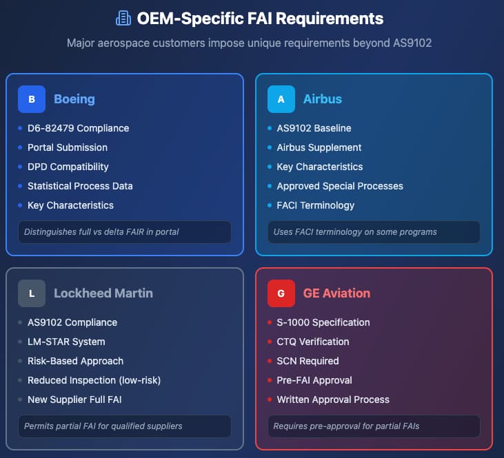
Major aerospace OEMs impose additional requirements beyond AS9102. Understanding these prevents approval delays.
Boeing FAI Requirements
Boeing requires:
- D6-82479 compliance for all FAIR
- First Article Inspection Report (FAIR) submission through Boeing Portal
- Digital Product Definition (DPD) compatibility for model-based definitions
- Statistical process data for critical characteristics (Key Characteristics)
Boeing distinguishes between full FAIR and delta FAIR clearly in their supplier portal. Suppliers must indicate FAI type at submission.
Airbus FAI Requirements
Airbus specifies:
- AS9102 compliance as baseline
- Airbus Supplement requirements for specific programs
- Key Characteristics (KC) identification and statistical reporting
- Special process validation from approved sources only
Airbus uses First Article Conformance Inspection (FACI) terminology for some programs. The requirements parallel AS9102 but include additional Airbus-specific forms.
Lockheed Martin FAI Requirements
Lockheed Martin mandates:
- AS9102 compliance
- LM-STAR system entry for certain commodities
- Risk-based FAI approach allowing reduced inspection for low-risk changes
Lockheed Martin permits partial FAIs for qualified suppliers with demonstrated process capability. New suppliers must perform full FAIs for initial deliveries.
General Electric Aviation FAI Requirements
GE Aviation requires:
- S-1000 specification compliance
- Critical to Quality (CTQ) characteristic verification
- Supplier Change Notification (SCN) before any FAI-triggering change
GE Aviation emphasizes pre-FAI approval for partial FAIs. Suppliers must obtain written approval before submitting partial documentation.
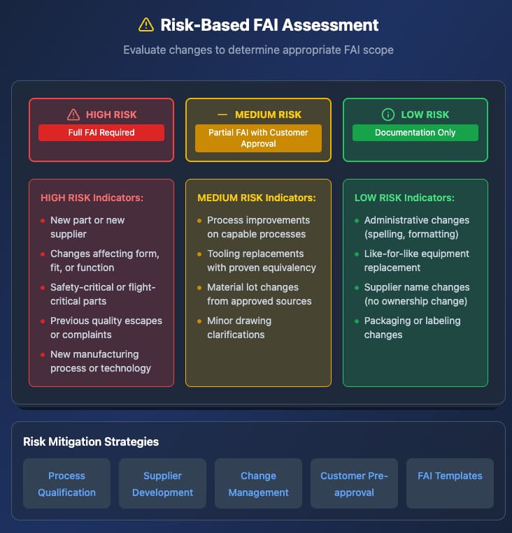
Risk-Based FAI Planning
Smart suppliers apply risk assessment to FAI decisions. This approach optimizes resources while maintaining compliance.
Risk Assessment Framework
Evaluate each potential FAI using these factors:
High Risk (Full FAI Required):
- New part or new supplier
- Changes affecting form, fit, or function
- Safety-critical or flight-critical parts
- Previous quality escapes or customer complaints
- New manufacturing process or technology
Medium Risk (Partial FAI with Customer Approval):
- Process improvements on capable processes
- Tooling replacements with proven equivalency
- Material lot changes from approved sources
- Minor drawing clarifications
Low Risk (Documentation Only):
- Administrative changes (spelling, formatting)
- Like-for-like equipment replacement
- Supplier name changes without ownership change
- Packaging or labeling changes
Risk Mitigation Strategies
Reduce FAI burden through:
1. Process qualification – Establish statistical capability before production
2. Supplier development – Qualify multiple approved sources
3. Change management – Implement robust ECN processes
4. Customer pre-approval – Seek partial FAI approval before changes
5. FAI templates – Standardize documentation for efficiency
Documentation Best Practices
Clear, complete documentation accelerates FAI approval. Follow these practices for every submission.
Form 1: Part Number Accountability
- List all associated drawings with current revisions
- Include purchase order and contract references
- Document software/firmware versions if applicable
- Reference previous FAI numbers for partial submissions
Form 2: Product Accountability
- Attach material certifications with full traceability
- List all special processes with supplier certifications
- Include functional test results and acceptance criteria
- Document calibration certificates for inspection equipment
Form 3: Characteristic Accountability
- Number every characteristic sequentially
- Record actual measured values (not “pass/fail”)
- Include drawing zone references for traceability
- Attach ballooned drawings showing characteristic locations
- Note any characteristics requiring engineering approval
Common Documentation Mistakes
Avoid these errors that delay approvals:
- Missing revision levels on drawings or specifications
- Incomplete material certifications lacking heat/lot numbers
- Unapproved special processes from non-qualified suppliers
- Missing balloon drawings making characteristic location unclear
- Incorrect FAI type selection (partial when full required)
Real-World FAI Scenarios
These examples illustrate practical FAI decision-making.
Scenario 1: CNC Program Update
- Situation: Updating a CNC program to improve surface finish on one feature.
- Analysis: The change affects one characteristic (surface finish) on an existing part with prior full FAI approval.
- Decision: Partial FAI verifying only the surface finish characteristic.
- Documentation: Form 3 with updated surface finish measurement; reference to previous full FAI.
Scenario 2: New Material Supplier
- Situation: Sourcing aluminum bar stock from a new mill for an existing part.
- Analysis: Material changes affect material properties, traceability, and potentially machinability.
- Decision: Full FAI required despite existing part history.
- Documentation: Complete Forms 1, 2, and 3 with new material certification and full dimensional verification.
Scenario 3: Engineering Drawing Revision
- Situation: Customer issues drawing revision adding one new hole and tightening one tolerance.
- Analysis: Engineering change affecting limited characteristics.
- Decision: Delta FAI verifying the new hole location and the tightened dimension.
- Documentation: Forms 1, 2, and 3 updated for revision change; Form 3 includes only the two changed characteristics.
Scenario 4: Tooling Replacement
- Situation: Replacing a worn fixture with an identical replacement.
- Analysis: Like-for-like tooling replacement on a capable process.
- Decision: Partial FAI verifying fixture-controlled dimensions.
- Documentation: Form 3 with dimensions controlled by the replaced tooling; engineering approval for partial FAI approach.
Key Takeaways
- Full FAI verifies every characteristic and applies to new parts, new suppliers, and major changes
- Partial FAI verifies only affected characteristics when previous full FAIs exist
- Delta FAI specifically addresses engineering changes and drawing revisions
- Customer requirements from Boeing, Airbus, and other OEMs add specific requirements beyond AS9102
- Risk-based FAI planning optimizes resources while maintaining compliance
- Clear documentation accelerates approval and prevents rejection
Conclusion
Understanding partial vs full first article inspection requirements protects your aerospace manufacturing business from costly delays and compliance issues. Apply the decision frameworks in this guide to streamline your FAI process while satisfying customer expectations.
Understanding when to apply a full versus partial first article inspection is not just about compliance, it is a strategic decision that directly impacts lead time, cost efficiency, and customer trust. By applying a structured, risk-based approach, suppliers can ensure that every change is validated appropriately while avoiding unnecessary full re-inspections. This balance allows manufacturers to maintain rigorous quality standards without slowing down production, ultimately strengthening both operational performance and customer relationships.
At Align Manufacturing, we bring this disciplined approach to every project, combining deep expertise in machining and supply chain management with a clear understanding of aerospace quality requirements. Whether supporting complex inspection scenarios or managing evolving customer specifications, our team ensures the right level of validation at every stage. With extensive experience across global manufacturing networks, including forging in Vietnam, Align Manufacturing helps clients achieve reliable, compliant, and efficient production outcomes with confidence.
FAQ: Partial vs Full First Article Inspection
What is the difference between partial FAI and full FAI?
Full FAI inspects every design characteristic on a part. Partial FAI inspects only characteristics affected by a specific change. Full FAIs apply to new parts, new suppliers, or major changes. Partial FAIs apply when previous full FAIs exist and changes are limited in scope.
When is partial FAI allowed?
Partial FAI is allowed when a previous full FAI exists, the change affects fewer than 50% of characteristics, and the change does not affect form, fit, or function. Customer approval is often required before submitting a partial FAI.
What triggers a full first article inspection?
Full FAIs are triggered by new part introduction, new supplier qualification, manufacturing location changes, process changes affecting form/fit/function, design revisions, and production lapses exceeding 24 months.
What is a delta FAI?
A delta FAI verifies characteristics affected by an engineering change. The term “delta” represents the difference between design revisions. Delta FAIs accompany engineering change notices and demonstrate compliance to revised requirements.
How is delta FAI different from partial FAI?
Delta FAI specifically addresses engineering changes (ECNs). Partial FAI addresses any change including process changes, tooling changes, or material changes that do not involve design revisions. Delta FAIs always involve drawing revisions; partial FAIs may not.
Do Boeing and Airbus accept partial FAIs?
Yes, both Boeing and Airbus accept partial FAIs when properly justified. Boeing requires portal submission with clear FAI type indication. Airbus requires compliance with their supplement requirements. Both may require pre-approval for partial FAIs depending on the program and part criticality.
What percentage of characteristics can a partial FAI cover?
Industry practice suggests partial FAIs should cover fewer than 50% of characteristics. If more than half of characteristics require verification, a full FAI is typically more efficient and less risky.
Can I perform a partial FAI for a new supplier?
No. New suppliers always require full FAIs for initial deliveries. Partial FAIs apply only when a previous full FAI exists for the same part manufactured at your facility.
How long is an FAI valid?
Full FAIs remain valid indefinitely unless triggered events occur. However, production lapses exceeding 24 months typically require new full FAIs. Customer-specific requirements may impose shorter validity periods.
What happens if I submit the wrong FAI type?
Submitting the wrong FAI type results in rejection, delays, and potential production holds. Customers may require corrective action plans and additional documentation. Repeated errors can affect supplier ratings and future business.
Is customer approval required for partial FAI?
Customer approval requirements vary by OEM and program. Boeing, Airbus, and Lockheed Martin typically require notification or approval for partial FAIs. Always check your specific contract and supplier quality requirements.
What documentation supports a partial FAI decision?
Support partial FAI decisions with change impact analysis, risk assessment, previous FAI references, and process capability data. Document why unaffected characteristics do not require re-verification.
Custom Architectural Brass: Machining, Forming, and Finishing for Design

A Technical Deep-Dive into Brass-Specific PFMEA for CNC Operations
In precision manufacturing, the difference between a component that performs flawlessly and one that fails under load often comes down to what you anticipated before the first chip hit the floor. Process Failure Mode and Effects Analysis (PFMEA) is the systematic methodology that separates reactive manufacturers from proactive ones,and when it comes to brass, a material with unique behavioral characteristics, generic FMEA templates simply won’t suffice.
For manufacturers working with architectural brass components, understanding material-specific failure modes isn’t optional. Galling, burr formation, work hardening, and dimensional drift each represent potential quality catastrophes that can derail production schedules, inflate costs, and damage client relationships. This guide provides a comprehensive framework for implementing brass-specific PFMEA in CNC operations, with practical applications for both high-volume production environments and specialized job shops serving the ASEAN manufacturing ecosystem.
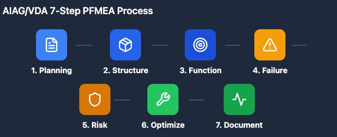
Section 1: PFMEA Fundamentals – The AIAG/VDA 7-Step Approach
Understanding the Methodology
The AIAG/VDA FMEA Handbook represents the current industry standard for process failure analysis, replacing the traditional 4th edition approach with a more structured seven-step methodology. This framework provides the foundation for identifying, evaluating, and mitigating risks before they manifest as actual failures.
The Seven Steps of PFMEA:
- Planning and Preparation: Define the scope, team, and timing of the analysis. For brass CNC operations, this includes identifying specific alloy grades (C36000, C46400, C93200) and their unique processing requirements.
- Structure Analysis: Break down the manufacturing process into individual process steps, work elements, and focus elements. A brass CNC operation might include: material receiving, setup/qualification, rough cutting, finish machining, deburring, and inspection.
- Function Analysis: Document what each process element is supposed to achieve. For brass finish machining, this might include achieving specified surface finish (Ra 0.8-1.6 μm), maintaining dimensional tolerances (±0.05mm), and preventing work hardening.
- Failure Analysis: Identify potential failure modes, their effects, and root causes. This is where brass-specific knowledge becomes critical—standard FMEA templates designed for steel or aluminum often miss material-specific failure mechanisms.
- Risk Analysis: Calculate Risk Priority Numbers (RPN) using Severity (S), Occurrence (O), and Detection (D) ratings. The new AIAG/VDA method replaces RPN with Action Priority (AP) levels, though RPN remains widely used in practice.
- Optimization: Develop and implement mitigation strategies to reduce risk. This includes process changes, additional controls, or design modifications.
- Results Documentation: Capture lessons learned and update the PFMEA as a living document.
Why Standard PFMEA Templates Fall Short for Brass
Generic PFMEA templates typically address common failure modes across all materials: dimensional variation, surface defects, and tool wear. However, brass, which a copper-zinc alloy with distinct mechanical properties, presents unique challenges that demand specialized attention:
- Galling tendency: Brass’s softness and low melting point create adhesion risks with cutting tools
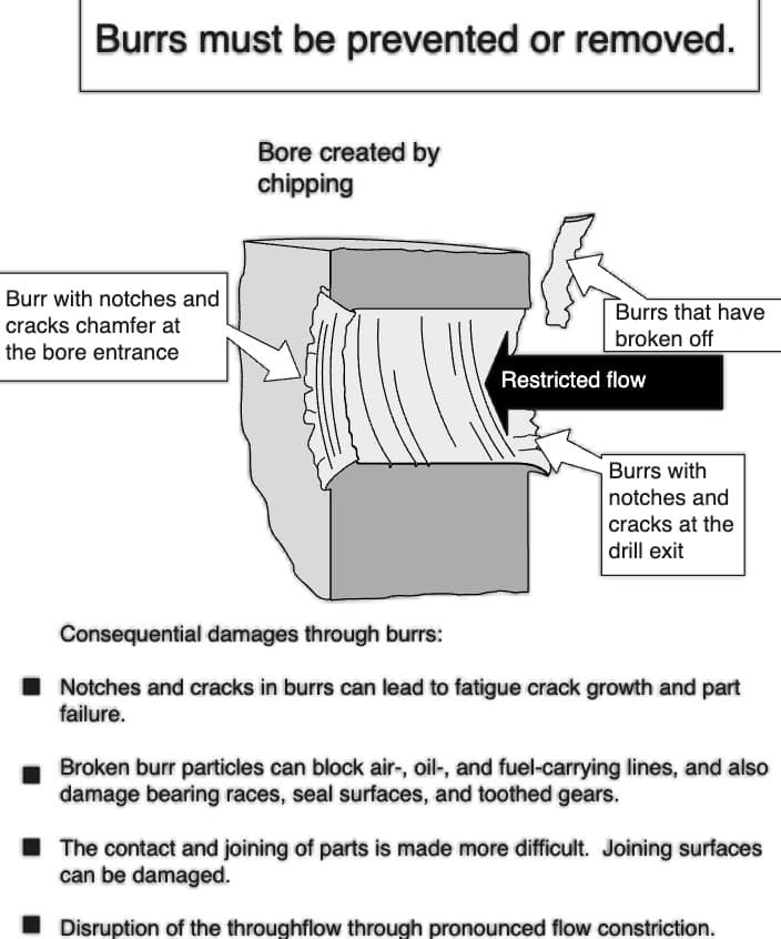
- Burr formation propensity: Ductility leads to burrs that are difficult to remove without surface damage
- Work hardening characteristics: Cold working can increase hardness by 20-30%, affecting subsequent operations
- Thermal conductivity: Rapid heat dissipation affects cutting temperatures and tool life
A PFMEA that doesn’t account for these brass-specific behaviors leaves manufacturers vulnerable to predictable, preventable failures.
Section 2: Brass Material Properties and Failure Mode Correlation
Understanding Brass Alloys in CNC Applications
Not all brass is created equal. The alloy composition directly impacts machinability, failure mode probability, and appropriate PFMEA severity ratings.
Common Architectural Brass Grades:
| Alloy | Composition | Machinability Rating | Key Characteristics | Primary Failure Risks |
| C36000 (Free-Cutting Brass) | 61.5% Cu, 35.5% Zn, 3% Pb | 100% (baseline) | Excellent machinability, lead content for chip breaking | Lead distribution uniformity, surface lead smearing |
| C46400 (Naval Brass) | 60% Cu, 39.25% Zn, 0.75% Sn | 30% | High corrosion resistance, added tin | Work hardening, galling with high-speed cutting |
| C93200 (Bearing Bronze) | 83% Cu, 7% Sn, 7% Pb, 3% Zn | 50% | High lead content, bearing applications | Porosity, lead segregation |
| C38500 (Architectural Bronze) | 57% Cu, 40% Zn, 3% Pb | 90% | Good for extrusions, architectural trim | Extrusion seam defects, anisotropic properties |
Material Property Correlation Table for PFMEA
When developing your PFMEA, correlate material properties with specific failure modes:
Thermal Conductivity (109-125 W/m·K):
- Failure Mode: Rapid heat dissipation causes cutting edge temperature fluctuations
- Effect: Thermal cracking of carbide inserts, dimensional instability
- Occurrence Rating: 6 (moderate to high for high-speed operations)
Ductility (40-55% elongation):
- Failure Mode: Excessive material deformation during cutting
- Effect: Burr formation, poor surface finish, dimensional creep
- Occurrence Rating: 7 (high for finishing operations)
Low Melting Point (900-940°C):
- Failure Mode: Built-up edge (BUE) formation on cutting tool
- Effect: Surface tearing, increased cutting forces, accelerated tool wear
- Occurrence Rating: 5 (moderate, depends on cutting speed)
Tendency to Work Harden:
- Failure Mode: Surface hardness increase during machining
- Effect: Reduced machinability in subsequent passes, increased tool wear, potential for cracking
- Occurrence Rating: 6 (moderate to high for interrupted cuts)
Section 3: CNC Operation Phases – Phase-Specific PFMEA
Phase 1: Setup and Qualification
The setup phase establishes the foundation for all subsequent operations. In brass machining, thermal expansion and workpiece stability are critical considerations.
Key Process Elements:
- Workpiece fixturing and clamping force
- Tool presetting and offset verification
- Machine warm-up and thermal stabilization
- First-piece qualification
Brass-Specific Failure Modes:
Failure Mode 1: Excessive Clamping Force
- Effect: Workpiece deformation, dimensional non-conformance
- Severity: 8 (customer dissatisfaction, potential assembly issues)
- Cause: Brass’s lower yield strength (124-310 MPa) compared to steel
- Current Controls: Torque-limited clamping fixtures, soft jaw design
- RPN: 8 × 6 × 4 = 192 (High Priority)
- Recommendation: Implement fixture pressure monitoring, specify maximum clamping force in setup sheets
Failure Mode 2: Thermal Expansion Misalignment
- Effect: Z-axis drift, incorrect depth of cut
- Severity: 7 (dimensional variation)
- Cause: Brass thermal expansion coefficient (20.5 × 10⁻⁶/°C) affecting positioning
- Current Controls: Machine warm-up procedures, ambient temperature monitoring
- RPN: 7 × 5 × 5 = 175 (High Priority)
Phase 2: Rough Cutting
Rough machining removes bulk material and establishes basic geometry. For brass, heat generation and chip evacuation are primary concerns.
Key Process Elements:
- Spindle speed selection (SFM optimization)
- Feed rate programming
- Depth of cut determination
- Coolant application strategy
Brass-Specific Failure Modes:
Failure Mode 3: Built-Up Edge Formation
- Effect: Poor surface finish, increased cutting forces, dimensional variation
- Severity: 7
- Cause: Brass adhesion to tool due to low melting point and high ductility
- Occurrence: 6 (common at moderate cutting speeds)
- Detection: 4 (visual inspection, surface finish measurement)
- RPN: 168
- Mitigation: Polished tool coatings (TiAlN, DLC), optimal cutting speeds (300-600 SFM), high-pressure coolant
Failure Mode 4: Chip Nesting and Evacuation Failure
- Effect: Surface scratching, tool damage, machine downtime
- Severity: 6
- Cause: Long, stringy chips typical of high-ductility brass alloys
- Occurrence: 5
- Detection: 3 (machine alarm, visual monitoring)
- RPN: 90
- Mitigation: Chip breakers, high-pressure through-spindle coolant, programmed chip breaks (peck drilling cycles)
Phase 3: Finish Machining
Finish operations determine final part quality and must account for brass’s propensity for surface deformation.
Key Process Elements:
- Finish tool path programming
- Final dimension achievement
- Surface finish generation
- Burr minimization
Brass-Specific Failure Modes:
Failure Mode 5: Burr Formation at Exit
- Effect: Additional deburring operations, potential surface damage, increased cycle time
- Severity: 6
- Cause: Brass ductility causes material tearing rather than clean shearing
- Occurrence: 8 (very high for through-features)
- Detection: 4 (visual inspection, touch probe verification)
- RPN: 192
- Mitigation: Exit chamfer programming, sharp cutting edges (hone radius <0.01mm), reduced feed at exit, back chamfer tools
Failure Mode 6: Work Hardening During Finishing
- Effect: Increased tool wear in subsequent operations, surface hardness variation
- Severity: 5
- Cause: Cold working from previous operations or aggressive cutting parameters
- Occurrence: 6
- Detection: 5 (microhardness testing, surface analysis)
- RPN: 150
- Mitigation: Intermediate annealing for complex parts, optimized tool paths minimizing rub, sharp cutting tools
Phase 4: Deburring and Finishing
Post-machining operations are critical for brass architectural components where aesthetics matter.
Key Process Elements:
- Mechanical deburring (tumbling, vibratory finishing)
- Manual deburring operations
- Surface treatment application
- Protective coating or patination
Brass-Specific Failure Modes:
Failure Mode 7: Surface Smearing During Deburring
- Effect: Visible surface defects, uneven patina absorption, rejected parts
- Severity: 8 (aesthetic failure on visible components)
- Cause: Brass softness allows abrasive media to embed or smear
- Occurrence: 6
- Detection: 3 (visual inspection under magnification)
- RPN: 144
- Mitigation: Ceramic media selection, controlled processing time, dedicated brass-only finishing equipment
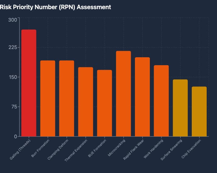
Failure Mode 8: Galling in Threaded Features
- Effect: Seized fasteners, stripped threads, field failures
- Severity: 9 (potential for complete part replacement)
- Cause: Adhesion between brass threads under load, especially with similar brass fasteners
- Occurrence: 5
- Detection: 6 (torque testing, thread gauge inspection)
- RPN: 270 (Critical Priority)
- Mitigation: Anti-seize compound specification, thread class tolerance optimization, dissimilar material fastener recommendations
Section 4: Brass CNC Failure Mode Library
Comprehensive Failure Mode Database
This reference library provides pre-evaluated failure modes specific to brass CNC operations, serving as a starting point for your PFMEA development.
Cutting Tool-Related Failures
| Failure Mode | Potential Effect | S | Cause | O | Current Control | D | RPN | Recommended Action |
| Built-up edge formation | Poor surface finish, dimensional drift | 7 | Low cutting speed, uncoated tools | 6 | Tool life monitoring | 4 | 168 | Implement minimum SFM requirements; specify polished tool coatings |
| Rapid flank wear | Loss of dimensional accuracy | 8 | Abrasive brass constituents, high cutting temps | 5 | Scheduled tool changes | 5 | 200 | Optimize cutting parameters; implement tool wear compensation |
| Chipping/cratering | Sudden tool failure, part damage | 9 | Intermittent cutting, vibration | 4 | Tool condition monitoring | 3 | 108 | Program smooth entry/exit; reduce radial engagement |
| Edge buildup transfer | Surface contamination | 6 | BUE break-off during cutting | 5 | In-process inspection | 4 | 120 | Increase coolant concentration; improve chip evacuation |
Workpiece-Related Failures
| Failure Mode | Potential Effect | S | Cause | O | Current Control | D | RPN | Recommended Action |
| Burr formation | Additional processing, surface damage | 6 | Ductile material behavior | 8 | Visual inspection | 4 | 192 | Optimize exit strategy; implement back chamfering |
| Dimensional drift | Assembly interference | 8 | Thermal expansion, work hardening | 5 | In-process probing | 4 | 160 | Thermal compensation algorithms; intermediate measurement |
| Surface tearing | Aesthetic rejection | 8 | Built-up edge, dull tools | 5 | Surface finish check | 3 | 120 | Tool condition protocols; cutting parameter optimization |
| Microcracking | Structural weakness, corrosion initiation | 9 | Excessive work hardening | 4 | Dye penetrant inspection | 6 | 216 | Stress relief annealing; process parameter review |
Process-Related Failures
| Failure Mode | Potential Effect | S | Cause | O | Current Control | D | RPN | Recommended Action |
| Chip evacuation failure | Surface damage, tool breakage | 7 | Stringy chips, inadequate coolant | 6 | Machine alarms | 3 | 126 | High-pressure coolant; chip conveyor maintenance |
| Work hardening | Reduced machinability | 6 | Excessive cold working | 6 | Hardness testing | 5 | 180 | Optimize depth of cut; consider annealing cycles |
| Galling (threaded features) | Seizure, fastener failure | 9 | Material adhesion under load | 5 | Torque testing | 6 | 270 | Anti-seize protocol; thread design review |
| Clamping deformation | Dimensional non-conformance | 8 | Excessive force on soft material | 6 | Setup verification | 4 | 192 | Torque-limited fixtures; soft jaw implementation |
Section 5: Case Study – Brass Architectural Component PFMEA Walkthrough
Scenario: Custom Brass Door Hardware Component
Part Description: Solid brass lever handle (C36000) requiring precision machining of mounting features, threaded insert bores, and aesthetic surfaces requiring mirror finish on visible faces.
Manufacturing Process Flow:
- Bar stock receiving and inspection
- CNC turning (rough and finish)
- CNC milling (mounting features)
- Thread milling (M8 mounting threads)
- Deburring and surface finishing
- Protective lacquer application
- Final inspection and packaging
Detailed PFMEA Excerpt
Process Step: CNC Turning – Finish Profile Function: Generate final handle profile to ±0.1mm tolerance with Ra 0.4 μm surface finish on visible surfaces
| Failure Mode | Potential Effect | S | Potential Cause | O | Current Prevention | Current Detection | D | RPN | Action Recommended | Resp | Target Date |
| Visible surface burr at shoulder | Customer rejection, aesthetic failure | 8 | Ductile material tearing at tool exit | 7 | Programmed lead-out; sharp tools | Visual inspection 100% | 3 | 168 | Implement back-turning operation; reduce feed 50% at exit | Process Eng | 15/06/2026 |
| Dimensional variation in diameter | Assembly interference or looseness | 8 | Thermal expansion during cutting; tool wear | 5 | Tool life tracking; constant SFM | In-process probing | 4 | 160 | Add diameter probe check mid-batch; implement tool wear compensation | QC Mgr | 22/06/2026 |
| Surface finish non-conformance (Ra > 0.4) | Aesthetic rejection, patina variation | 7 | BUE formation; improper feed/speed | 6 | Parameter cards; coated inserts | Surface roughness check | 4 | 168 | Specify TiAlN coated inserts; optimize feed to 0.1mm/rev | Manufacturing Eng | 15/06/2026 |
| Work hardening in bore | Thread milling difficulty, tool wear | 6 | Aggressive roughing parameters | 6 | Roughing parameter limits | Hardness spot check | 5 | 180 | Reduce roughing depth of cut; add stress-relief anneal step | Materials Eng | 29/06/2026 |
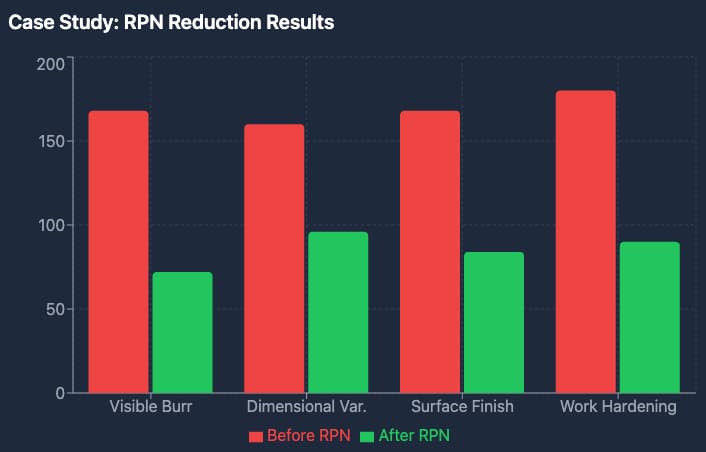
Post-Implementation Results: Following implementation of recommended actions, the RPN values were reduced as follows:
- Visible burr: 168 → 72 (57% reduction)
- Dimensional variation: 160 → 96 (40% reduction)
- Surface finish: 168 → 84 (50% reduction)
- Work hardening: 180 → 90 (50% reduction)
First-pass yield improved from 87% to 96%, and customer complaints related to surface quality dropped to zero over a six-month period.
Section 6: SPC Integration – From PFMEA to Control Plans
Linking PFMEA to Statistical Process Control
A PFMEA without integration to Statistical Process Control (SPC) is a theoretical exercise. The true value emerges when failure mode prevention translates to real-time process monitoring.
Control Plan Development from PFMEA:
For each high-RPN failure mode identified in your PFMEA, develop corresponding control plan elements:
- Control Method: How will you prevent or detect the failure?
- Measurement Technique: What specific measurement tools and methods apply?
- Sample Size/Frequency: How often and how many samples?
- Control Limits: What constitutes acceptable vs. concerning variation?
- Reaction Plan: What happens when controls indicate a problem?
SPC Chart Selection for Brass CNC Operations
| Failure Mode | SPC Chart Type | Rationale | Key Variables |
| Dimensional drift | X-bar and R Chart | Monitor central tendency and variation simultaneously | Critical dimensions (diameter, length) |
| Surface finish | Individual-X and Moving Range | Destructive or expensive measurement, low volume | Ra values from surface profilometer |
| Tool wear trend | CUSUM or EWMA | Detect small, persistent changes before they become problems | Tool length compensation values |
| Burr occurrence | p-chart or np-chart | Attribute data (pass/fail), track proportion defective | Burr presence at critical features |
| Work hardening | Individual-X | Batch processing, moderate frequency | Microhardness readings |
Control Plan Example: Brass Finish Turning
Control Plan Reference: CP-BR-FT-001 Part/Process: Finish turning operation on C36000 brass components PFMEA Reference: PFMEA-BR-003
| Characteristic | Specification | Control Method | Measurement | Sample Size | Frequency | Control Limits | Reaction Plan |
| Diameter | 25.00 ± 0.05mm | X-bar & R Chart | CMM or micrometer | 5 parts | Hourly | UCL: 25.03, LCL: 24.97 | Stop production; adjust offset; quarantine last hour |
| Surface finish | Ra ≤ 0.8 μm | Individual-X | Surface profilometer | 1 part | Every 4 hours | UCL: 0.7 μm | Replace insert; inspect last 10 parts |
| Burr presence | No visible burrs | Attribute check | Visual/magnification | 100% | Continuous | 0 defects | Rework part; adjust tool path |
| Tool wear | < 0.05mm flank wear | Tool presetting | Tool scope | All tools | Per change | Max 0.05mm | Change tool; inspect first part |
Digital Integration: PFMEA to MES Systems
Modern Manufacturing Execution Systems (MES) can integrate PFMEA data directly into production workflows:
- Automated Inspection Triggers: High-RPN failure modes automatically generate inspection work instructions
- Real-time Alerts: SPC violations trigger immediate notifications to production and quality personnel
- Closed-loop Feedback: Inspection results feed back into PFMEA occurrence ratings for continuous improvement
- Traceability: Complete part genealogy linking material lots, process parameters, and inspection results
Section 7: Job Shop vs. Production PFMEA Adaptation
The Small-Batch Challenge
Job shops face unique PFMEA challenges compared to mass production facilities:
- Lower volume: Statistical data may be limited or non-existent for specific part numbers
- Higher variety: Each new part requires PFMEA development from scratch or adaptation
- Resource constraints: Limited quality engineering bandwidth for comprehensive analysis
- Customer variability: Different clients may have conflicting quality requirements
Adaptive PFMEA Strategies for Job Shops
Strategy 1: Generic Process PFMEA Templates
Develop master PFMEAs for process families rather than individual parts:
- Template: Brass Turning Operations (C36000)
- Template: Brass Milling Operations (All Alloys)
- Template: Brass Thread Generation
When a new part arrives, adapt the template rather than starting from zero.
Strategy 2: Risk-Based Sampling
Not all features require the same level of scrutiny:
- Class A (Critical): Safety-related, customer-specified critical, tight tolerances (< ±0.05mm)
- Approach: Full PFMEA with all recommended actions implemented
- Class B (Major): Functional but not safety-critical, moderate tolerances (±0.05-0.2mm)
- Approach: Standard PFMEA with actions for RPN > 150
- Class C (Minor): Aesthetic or non-critical, loose tolerances (> ±0.2mm)
- Approach: Abbreviated PFMEA focusing on highest-risk failure modes only
Strategy 3: Pre-validated Process Windows
Establish proven parameter ranges for brass machining:
| Operation | Cutting Speed (SFM) | Feed Rate (mm/rev) | Depth of Cut (mm) | Validated For |
| Rough Turning | 400-600 | 0.15-0.25 | 2.0-5.0 | C36000, C38500 |
| Finish Turning | 500-800 | 0.05-0.15 | 0.25-1.0 | C36000, C38500 |
| Rough Milling | 300-500 | 0.10-0.20 | 3.0-6.0 | All brass grades |
| Finish Milling | 400-700 | 0.05-0.10 | 0.2-0.5 | All brass grades |
When parameters stay within validated windows, certain failure modes can be assigned lower occurrence ratings.
ASEAN Manufacturing Context
For manufacturers operating in or sourcing from ASEAN markets, additional PFMEA considerations apply:
Supplier Quality Variability:
- Material certification verification (mill test reports)
- Incoming material hardness/conductivity testing
- Traceability requirements for architectural applications
Environmental Factors:
- High humidity effects on corrosion-prone brass grades
- Temperature variations affecting machine accuracy
- Power quality impacts on CNC control systems
Workforce Considerations:
- Training requirements for PFMEA methodology
- Language barriers in technical documentation
- Cultural factors in quality escalation procedures
Section 8: RPN Calculation and Action Priority Guidelines
Understanding Risk Priority Numbers
While the AIAG/VDA handbook has shifted toward Action Priority (AP) ratings, RPN remains widely used in practice. Understanding RPN calculation ensures consistent risk evaluation.
RPN Formula: RPN = Severity (S) × Occurrence (O) × Detection (D)
Rating Scales (Traditional AIAG 4th Edition):
| Rating | Severity (Effect on Customer) | Occurrence (Probability) | Detection (Chance of Finding) |
| 1 | No effect | ≤ 1 in 1,500,000 | Almost certain (error-proofed) |
| 2-3 | Minor annoyance | 1 in 150,000 – 1 in 15,000 | High probability |
| 4-6 | Moderate effect | 1 in 2,000 – 1 in 100 | Moderate probability |
| 7-8 | High impact | 1 in 50 – 1 in 10 | Low probability |
| 9-10 | Safety/critical | ≥ 1 in 5 | Very low/none |
RPN Threshold Guidelines for Brass CNC Operations
| RPN Range | Priority | Action Required |
| 1-80 | Low | Monitor; no immediate action unless easy improvement |
| 81-150 | Moderate | Action recommended; schedule based on resources |
| 151-250 | High | Action required; prioritize above routine work |
| 251-400 | Critical | Immediate action; escalate to management |
| 401-1000 | Emergency | Stop production until mitigated |
Special Considerations for Brass
Severity Overrides: Even with low RPN, certain failure modes require attention:
- Any safety-related failure (Severity 9-10): Action required regardless of RPN
- Galling in structural threads: Considered critical for architectural hardware
- Stress corrosion cracking potential: Elevated severity for outdoor applications
Detection Challenges: Brass-specific inspection difficulties:
- Microcracks in complex geometries may require dye penetrant (lower detection rating)
- Subsurface work hardening requires destructive testing (very low detection)
- Surface smearing may mask underlying defects (reduced detection effectiveness)
Conclusion
Process Failure Mode and Effects Analysis is not a checkbox exercise, it is a living methodology that, when properly implemented, transforms reactive quality management into proactive risk mitigation. For brass CNC operations, the difference between a generic PFMEA and a material-specific analysis can mean the difference between consistent first-pass yield and recurring quality issues.
The framework presented in this guide provides a comprehensive starting point for brass-specific PFMEA implementation. However, the true value emerges when teams apply these principles to their specific equipment, processes, and customer requirements. Document learnings, continuously update PFMEAs as processes evolve, and treat each failure, whether it’s anticipated or not, as an opportunity to strengthen risk assessment and control.
For job shops and production facilities alike, the investment in a robust PFMEA process delivers measurable returns through reduced rework, improved customer confidence, and more predictable production outcomes. At Align Manufacturing, we apply these principles across our operations in Vietnam’s machining sector, integrating PFMEA with real-time process control and continuous improvement systems to ensure consistent quality and long-term reliability.
The components leaving your facility today carry your reputation into the market for years to come. A disciplined PFMEA approach ensures that legacy is defined by precision, reliability, and manufacturing excellence.
Appendix: Quick Reference Tables
Brass Grade Quick Selector for PFMEA
| Application | Recommended Grade | Key PFMEA Focus |
| Interior hardware (high machinability) | C36000 | Lead distribution, surface smearing |
| Exterior/marine hardware | C46400 | Work hardening, galling prevention |
| Bearing surfaces | C93200 | Porosity, lead segregation |
| Architectural extrusions | C38500 | Anisotropic properties, seam defects |
Cutting Parameter Quick Reference
| Operation | SFM Range | Feed (mm/rev) | Depth (mm) | Coolant |
| Rough Turn | 400-600 | 0.15-0.25 | 2.0-5.0 | Flood soluble |
| Finish Turn | 500-800 | 0.05-0.15 | 0.25-1.0 | High-pressure |
| Rough Mill | 300-500 | 0.10-0.20 (per tooth) | 3.0-6.0 | Through-spindle |
| Finish Mill | 400-700 | 0.05-0.10 (per tooth) | 0.2-0.5 | Mist/minimal |
Common Brass Failure Mode Causes
| Failure Mode | Most Common Causes | Quick Check |
| Burr formation | Dull tools, fast exit feed, high ductility | Tool condition; exit strategy |
| Galling | Similar materials, no lubrication, high load | Fastener material; anti-seize use |
| Work hardening | Large depths of cut, slow speeds, dull tools | Cutting parameters; tool sharpness |
| Built-up edge | Moderate speeds, uncoated tools, high ductility | Cutting speed; tool coating |
| Dimensional drift | Thermal effects, tool wear, machine warm-up | Thermal compensation; tool life tracking |
FAQ: Brass PFMEA and CNC Machining Risk Control
1. What is PFMEA in CNC machining?
PFMEA (Process Failure Mode and Effects Analysis) is a structured method used to identify potential failures in a manufacturing process before they occur. It helps manufacturers anticipate risks, evaluate their impact, and implement controls to prevent defects and improve overall process reliability.
2. Why is PFMEA especially important for brass machining?
Brass has unique material properties, such as high ductility, low melting point, and tendency to gall or form burrs, that introduce specific risks during machining. A brass-specific PFMEA ensures these failure modes are identified and controlled, rather than overlooked by generic templates.
3. What are the most common failure modes in brass CNC operations?
Typical brass-related failure modes include:
- Burr formation during cutting
- Built-up edge (BUE) on cutting tools
- Work hardening affecting subsequent operations
- Galling in threaded components
- Dimensional drift due to thermal expansion
These issues can impact both functional performance and surface quality if not properly managed.
4. How does PFMEA improve machining quality and efficiency?
PFMEA improves operations by:
- Reducing scrap and rework
- Increasing first-pass yield
- Identifying process weaknesses early
- Standardizing preventive controls
- Supporting consistent production outcomes
It shifts manufacturing from reactive problem-solving to proactive risk management.
5. What is RPN and how is it used in PFMEA?
RPN (Risk Priority Number) is calculated by multiplying:
- Severity (S)
- Occurrence (O)
- Detection (D)
This score helps prioritize which failure modes require immediate action, with higher values indicating greater risk.
6. How does PFMEA connect to SPC (Statistical Process Control)?
PFMEA identifies high-risk areas, while SPC monitors them in real time. For example:
- Dimensional drift → tracked with X-bar & R charts
- Surface finish → monitored using individual measurements
- Burr defects → tracked with attribute charts
Together, they create a closed-loop system for continuous quality control.
7. Can small job shops realistically implement PFMEA?
Yes. Job shops can adopt simplified strategies such as:
- Using template-based PFMEAs for common processes
- Focusing only on high-risk features
- Applying risk-based prioritization rather than full-scale analysis
This makes PFMEA practical even in high-mix, low-volume environments.
8. How often should PFMEA be updated?
PFMEA should be treated as a living document and updated when:
- New materials or processes are introduced
- Customer requirements change
- Failures or defects occur
- Process improvements are implemented
Regular updates ensure the analysis remains relevant and effective.
9. What role does PFMEA play in customer confidence?
A well-implemented PFMEA demonstrates that a manufacturer proactively manages risk and quality. This builds trust with customers, especially those in industries where reliability, traceability, and consistency are critical.
10. How does PFMEA support manufacturing in Southeast Asia?
In regions with varying supplier capabilities, PFMEA helps standardize quality expectations and reduce variability. For manufacturers operating in or sourcing from ASEAN markets, particularly in precision machining and forging in Vietnam, PFMEA ensures consistent process control, improved reliability, and better alignment with international quality standards.
Navigating Lead-Free Brass (LFBR) Standards for Manufacturing

Introduction: The Regulatory Shift
For over a century, lead was considered essential in brass alloys. Added at 1-4% by weight, lead provided the machinability that made brass economical for mass production. But lead is toxic and is particularly dangerous to children’s neurological development, thus leading to regulators worldwide to eliminate it from drinking water systems.

The transition to lead-free brass (LFBR) represents one of the most significant material changes in plumbing and valve manufacturing history. For manufacturers, navigating this shift requires understanding not just the regulatory landscape, but the metallurgical implications of lead-free alloys and how they affect machinability, performance, and cost.
The Regulatory Landscape
United States Requirements for Lead-Free Brass
Reduction of Lead in Drinking Water Act (RLDWA)
- Effective: January 4, 2014
- Requirement: Maximum 0.25% weighted average lead content
- Scope: All pipes, pipe fittings, plumbing fittings, and fixtures
- Previous standard: 8% lead content (per SDWA Section 1417)
NSF/ANSI Standards
| Standard | Scope | Key Requirements |
| NSF/ANSI 61 | Drinking water system components | Lead extraction limits after 17-day exposure |
| NSF/ANSI 372 | Lead content verification | 0.25% maximum lead content |
| NSF/ANSI 358 | Polymer piping systems | Lead-free requirements for fittings |
California Proposition 65
- Requires warnings for lead exposure
- “No significant risk level” for lead: 0.5 μg/day
- Significant liability for non-compliance
International Requirements
European Union
| Regulation | Requirement |
| EU Drinking Water Directive (2020/2184) | Lead limit 10 μg/L in drinking water; member states reducing to 5 μg/L |
| REACH | Lead restricted in consumer products |
| EN 15664 | Influence of materials on water quality |
Canada
- NSFCAN 61 and 372 mirror US NSF standards
- Health Canada lead guideline: 5 μg/L
Asia-Pacific
| Country/Region | Standard | Requirement |
| Australia | AS/NZS 4020 | Lead extraction testing |
| Japan | JIS standards | Lead-free requirements expanding |
| China | GB standards | Varies by application |
| Thailand | TIS standards | Following international trends |
Lead-Free Brass Alloy Alternatives
The Challenge: Replacing Lead’s Function
Lead in brass serves two primary functions:
- Chip breaking: Lead embrittles chips, making them break rather than string
- Lubrication: Lead smears across tool faces, reducing friction
Without lead, brass becomes more difficult to machine as tools wear faster, surface finishes suffer, and cycle times increase.
Lead-Free Alloy Categories
1. Bismuth Brass
| Alloy | UNS | Bi Content | Characteristics |
| Eco Brass | C89325 | 2.5-3.5% | Good machinability, excellent corrosion resistance |
| Bismuth Brass 1 | C89320 | 1.5-3.0% | Direct C36000 replacement |
Machinability: 85-90% of C36000
Color: Similar to leaded brass
Cost: 15-25% premium over leaded
Applications: Plumbing fittings, valves, hardware
2. Silicon Brass
| Alloy | UNS | Si Content | Characteristics |
| Silicon Brass | C69300 | 2.5-3.5% | Excellent machinability, lead-free |
| Silicon Red Brass | C87300 | 3.0-4.0% | Casting alloy, excellent fluidity |
Machinability: 90-95% of C36000
Color: Slightly golden vs. yellow
Cost: 20-30% premium
Applications: High-performance plumbing, marine
3. Tin Brass (Low-Lead)
| Alloy | UNS | Characteristics |
| Semi-Red Brass | C83600 | <0.25% Pb, good castability |
| Leaded Red Brass (legacy) | C83600 | 4-6% Pb, no longer for potable water |
Note: C83600 now produced in low-lead versions for compliance
4. High-Performance Alternatives
| Alloy | UNS | Characteristics | Premium |
| Copper-Nickel | C70600 | Excellent seawater corrosion | 200%+ |
| Stainless Steel | 316L | Maximum corrosion resistance | 150%+ |
| Bronze | C83600 | Traditional, lead-free versions | 40%+ |
Machining Lead-Free Brass
Comparative Machinability
| Alloy | Machinability Rating | Relative to C36000 | Tool Life |
| C36000 (Leaded) | 100% (baseline) | 1.0× | Baseline |
| C69300 (Silicon) | 90-95% | 0.95× | -10% |
| C89325 (Bismuth) | 85-90% | 0.88× | -15% |
| C26000 (Cartridge) | 30% | 0.30× | -50% |
| C36000 (No Lead) | 40% | 0.40× | -40% |
Tooling Adjustments for LFBR
Cutting Tools
| Parameter | Leaded Brass | LFBR Recommendation | Rationale |
| Tool material | HSS or Carbide | Premium Carbide or Coated | Higher cutting forces |
| Coating | Optional | TiN, TiAlN recommended | Reduces built-up edge |
| Rake angle | 5-10° | 8-12° | Reduces cutting force |
| Clearance angle | 5-7° | 7-10° | Reduces rubbing |
| Nose radius | Standard | Reduced slightly | Better chip control |
Cutting Parameters
| Parameter | Leaded Brass | LFBR Adjustment |
| Surface Speed (SFM) | 400-800 | Reduce 10-20% |
| Feed Rate (IPR) | 0.005-0.015 | Reduce 10-15% |
| Depth of Cut | Full depth | Reduce 20% or increase passes |
| Coolant | Optional | Recommended |
| Coolant Type | Soluble oil | High-lubricity synthetic |
Chip Control Strategies
The Challenge LFBR produces long, stringy chips rather than broken chips:
- Safety hazard (stringy chips wrap around tools, parts, operators)
- Poor surface finish from chip recutting
- Increased heat generation
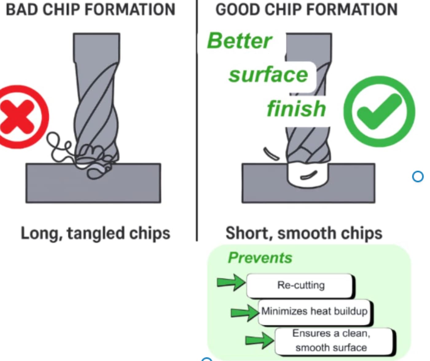
Solutions
| Strategy | Implementation |
| High-pressure coolant | 1000+ PSI directed at cutting zone |
| Chip breakers | Ground into tool geometry |
| Peck drilling | Interrupt cut to break chips |
| Oscillating feeds | Vary feed rate to vary chip thickness |
| Through-spindle coolant | For deep-hole drilling |
| Air blast | Supplement coolant for chip evacuation |
Tool Life Management
Expected Changes
| Tool Type | Leaded Brass Life | LFBR Life | Impact |
| Drill bits | 10,000 holes | 6,000-8,000 holes | -20-40% |
| End mills | 50 parts | 35-40 parts | -20-30% |
| Taps | 5,000 holes | 3,000-4,000 holes | -20-40% |
| Inserts | 4 hours | 3 hours | -25% |
Cost Mitigation
- Buy coated tools in volume
- Implement tool life monitoring
- Consider indexable vs. solid tools
- Negotiate consignment tooling agreements
Design Considerations for LFBR
Geometry Modifications
To improve machinability of LFBR components:
| Feature | Leaded Design | LFBR Optimization |
| Internal corners | Sharp corners | Radius minimum 0.015″ |
| Deep holes | L/D ratio 4:1 | Reduce to 3:1 or peck |
| Thin walls | 0.030″ | Increase to 0.050″ |
| Threads | Cut to full depth | Reduce engagement 75% |
| Surface finish | 32 μin Ra | Specify 63 μin Ra acceptable |
| Tight tolerances | ±0.001″ | Loosen to ±0.002″ where possible |
Surface Finish Expectations
| Alloy | Typical Ra (μin) | Best Achievable | Notes |
| C36000 | 16-32 | 8 | Excellent finish |
| C69300 | 32-63 | 16 | Good with proper tooling |
| C89325 | 32-63 | 16 | Good with proper tooling |
| C26000 | 63-125 | 32 | Requires optimization |
Tolerance Adjustments
LFBR work-hardens more readily than leaded brass:
- Allow for springback in forming operations
- Consider stress-relief annealing between operations
- Tighter process control required
Quality Control for LFBR
Material Verification
Incoming Inspection
- XRF (X-Ray Fluorescence) testing mandatory
- Verify lead content <0.25%
- Check silicon or bismuth content per specification
- Retain samples with heat/lot traceability
Testing Protocol
| Test | Method | Frequency | Acceptance |
| Chemistry | XRF or OES | Each lot | <0.25% Pb |
| Hardness | Rockwell B | Each lot | Per specification |
| Microstructure | Metallography | Sampling | No lead segregation |
| Corrosion | ISO 6509 | Quarterly | No dezincification |
Production Monitoring
In-Process Checks
- Tool wear monitoring (shorter intervals)
- Dimensional checks (thermal expansion differs)
- Surface finish verification
- Chip form assessment
First Article Requirements
- Full dimensional report
- Material certification review
- Surface finish measurement
- Torque testing (for threaded components)
- Pressure testing (for pressure-containing parts)
Cost Analysis
Material Cost Premium
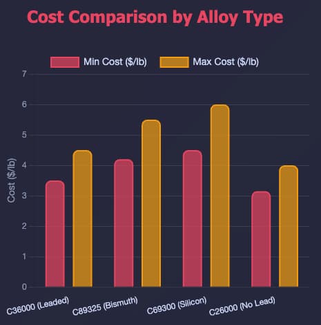
| Alloy | Cost vs. C36000 | 2026 Est. ($/lb) |
| C36000 (Leaded) | Baseline | ₫189,000–₫243,000/kg ($3.50–$4.50/lb) |
| C89325 (Bismuth) | +15-25% | ₫226,800–₫297,000/kg ($4.20–$5.50/lb) |
| C69300 (Silicon) | +20-30% | ₫243,000–₫324,000/kg ($4.50–$6.00/lb) |
| C26000 (No lead) | -10% to baseline | ₫170,100–₫216,000/kg ($3.15–$4.00/lb) |
Total Cost Impact
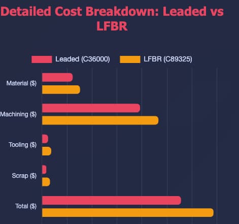
Example: 2″ Brass Valve Body
| Cost Factor | Leaded (C36000) | LFBR (C89325) | Change |
| Material | ₫61,250 ($2.50) | ₫75,950 ($3.10) | +24% |
| Machining (cycle time) | ₫196,000 ($8.00) | ₫232,750 ($9.50) | +19% |
| Tooling (amortized) | ₫12,250 ($0.50) | ₫18,375 ($0.75) | +50% |
| Scrap rate (3% vs 5%) | ₫8,575 ($0.35) | ₫15,925 ($0.65) | +86% |
| Total per part | ₫278,075 ($11.35) | ₫343,000 ($14.00) | +23% |
Cost Mitigation Strategies
- Near-net-shape forming: Reduce machining (forging, casting)
- Optimized toolpaths: CAM software optimized for LFBR
- High-speed machining: Compensate with speed where possible
- Volume purchasing: Negotiate LFBR material contracts
- Customer education: Price adjustment for compliance value
Southeast Asia Manufacturing Context
Regional LFBR Availability
Thailand
- Limited domestic LFBR production
- Primary alloys available: C69300 (imported), C89325 (limited)
- Most LFBR imported from Japan, Korea, or Europe
- Higher costs due to import duties and shipping
Supply Chain Recommendations
- Establish relationships with LFBR-certified distributors
- Consider stocking programs for volume products
- Plan 8-12 week lead times for specialty alloys
- Validate local testing capabilities (XRF)
Regulatory Trends
Thailand Water Supply Regulations
- Ministry of Public Health following international standards
- Lead limits in drinking water being reduced
- Expect alignment with EU/USA standards within 5-10 years
ASEAN Harmonization
- ASEAN Economic Community driving standard alignment
- Regional certification mutual recognition developing
- Export-oriented manufacturers should adopt strictest applicable standard
Export Market Requirements
| Destination | Standard | Certification Needed |
| USA | NSF/ANSI 61, 372 | NSF certification |
| EU | EN 15664, EN 12502 | CE marking, testing |
| Canada | NSF/ANSI 61, 372 | cNSF certification |
| Australia | AS/NZS 4020 | WaterMark certification |
Conclusion
Navigating the transition to lead-free brass requires more than simply replacing one alloy with another. It demands a deeper understanding of material behavior, machining implications, regulatory compliance, and cost trade-offs. From bismuth and silicon brass to high-performance alternatives, each material presents its own balance of machinability, corrosion resistance, and production efficiency.
As global standards continue to tighten, manufacturers must adopt a proactive approach by implementing robust quality control systems, optimizing machining strategies, and designing parts specifically for lead-free materials. The ability to manage chip control, tool wear, and process stability becomes increasingly critical in maintaining both quality and cost competitiveness.
In this evolving landscape, material selection and process strategy go hand in hand. At Align Manufacturing, we support our partners by integrating advanced manufacturing approaches, including near-net-shape techniques and optimized investment casting materials, to reduce machining burden while maintaining compliance and performance. This integrated approach not only ensures adherence to global standards but also strengthens long-term competitiveness in a rapidly changing supply chain.
FAQ
Q1: Can we still use leaded brass for non-potable applications?
A: Yes, but with caveats:
- Industrial, non-drinking water applications may still use leaded brass
- Must ensure no cross-connection to potable systems
- Some jurisdictions restrict leaded brass entirely
- Consider customer preference as many want lead-free even where not required
- Best practice: Transition to LFBR across all product lines
Q2: Is LFBR as corrosion-resistant as leaded brass?
A: Generally yes, and sometimes better:
- Bismuth brass (C89325): Comparable corrosion resistance
- Silicon brass (C69300): Superior dezincification resistance
- Silicon brass: Better saltwater performance than C36000
- No lead = no lead leaching = better for long-term potable water
Q3: Can we recycle LFBR the same as leaded brass?
A: With segregation:
- LFBR should be separated from leaded brass scrap
- Mixed scrap complicates recycling and may compromise compliance
- Some recyclers pay premium for segregated LFBR
- Mark LFBR parts clearly for end-of-life identification
Q4: Will LFBR tarnish or patina differently than leaded brass?
A: Slight differences:
- Silicon brass may develop slightly different patina color
- Bismuth brass patina very similar to leaded
- Both develop protective patina over time
- Overall appearance and protective qualities equivalent
Q5: Can we substitute C69300 directly for C36000?
A: With adjustments:
- Yes for chemistry compliance (<0.25% Pb)
- Yes for corrosion performance (C69300 superior)
- With caution for machining (adjust parameters)
- Verify for specific applications (pressure ratings may differ)
- Check with customers for specification acceptance
Q6: How do we handle legacy inventory of leaded brass parts?
A: Options:
- Non-potable markets: Sell to industrial applications if legal
- Recycling: Return to mill for credit
- Rework: Machine to LFBR if specifications permit
- Write-off: Scrap and claim loss
- Export: Markets with less stringent requirements (declining)
Never install leaded brass in potable water systems.
Q7: Do we need new tooling for every LFBR alloy?
A: Not necessarily:
- General-purpose carbide tooling works across LFBR alloys
- Optimize parameters per alloy
- Some high-performance coatings benefit all LFBR machining
- Keep leaded brass tools separate to avoid cross-contamination
Q8: How do we prove compliance to customers?
A: Documentation package:
- Mill certification showing <0.25% Pb
- XRF test results (incoming inspection)
- NSF/ANSI 372 certification (if required)
- Material safety data sheet
- Traceability records (heat/lot to finished part)
- Third-party test reports (if specified)
PPAP Levels 1–5 Explained for CNC Machining and Fabrication Suppliers
Introduction: What is PPAP and Why It Matters To Machining and Fabrication Suppliers
The Production Part Approval Process (PPAP) is the gold standard for quality verification in manufacturing supply chains. Developed by the automotive industry and now widely adopted across aerospace, medical device, and industrial equipment sectors, PPAP ensures that suppliers can consistently produce parts that meet all customer engineering requirements.
For CNC machining and fabrication suppliers, understanding PPAP isn’t optional, it’s a competitive necessity. OEMs increasingly require PPAP submission before awarding contracts, and the level of documentation required directly impacts quoting, lead times, and project complexity.
This guide explains PPAP Levels 1 through 5 specifically for CNC machining and fabrication suppliers, helping you understand which level applies to your projects, what documentation is required, and how to streamline your PPAP submission process.
Understanding the PPAP Framework
What is PPAP?
PPAP is a standardized process defined by AIAG (Automotive Industry Action Group) that helps suppliers demonstrate their capability to produce parts consistently meeting specifications. The process requires suppliers to submit documentation proving that:
- All engineering design records and specifications are properly understood
- The manufacturing process can produce conforming parts
- Production capacity meets volume requirements
- Quality control systems can detect and prevent defects
When is PPAP Required For Machining and Fabrication Suppliers?
PPAP submission is typically required for:
- New part introductions
- Engineering changes to existing parts
- Changes to manufacturing process, tools, or location
- Material or supplier changes
- Resumption of production after extended shutdown
- Annual revalidation (in some industries)
For CNC machining and fabrication shops, PPAP is most commonly required when supplying to:
- Tier 1 and Tier 2 automotive suppliers
- Aerospace manufacturers (AS9102 is similar but distinct)
- Medical device companies
- Heavy equipment OEMs
- Any customer following IATF 16949 or similar quality standards
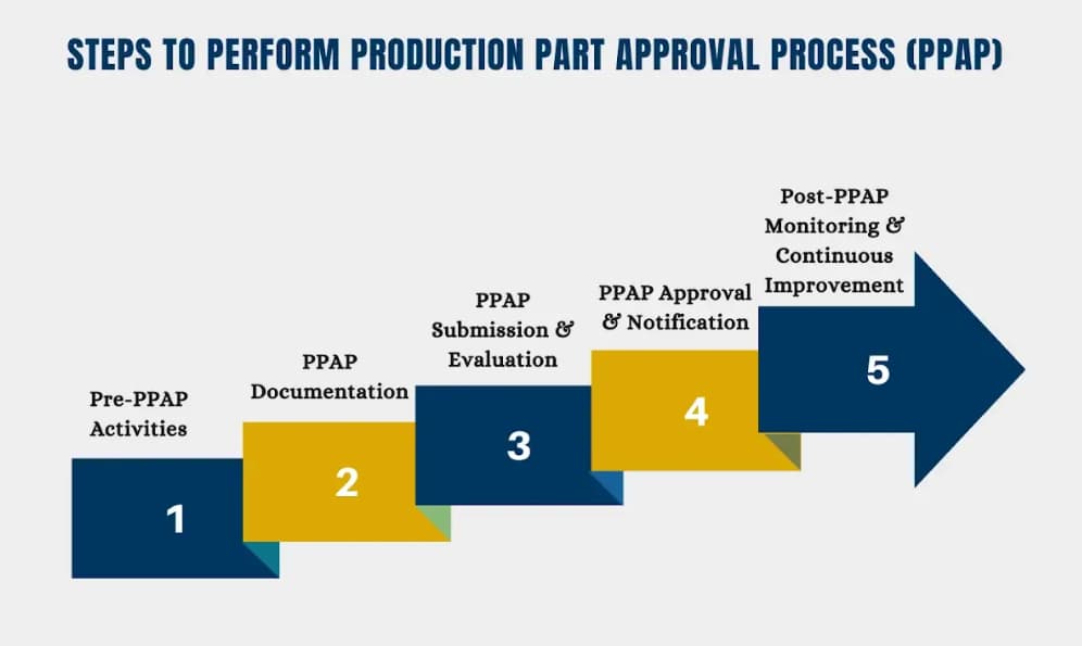
PPAP Level 1: Part Submission Warrant (PSW) Only
When to Use Level 1 for Machining and Fabrication
Level 1 is the minimal PPAP submission, requiring only the Part Submission Warrant. It’s typically used for:
- Designated appearance items where dimensional or functional verification isn’t required
- Low-risk components with extensive production history
- Internal approvals or engineering verification builds
- Parts with documented previous approval under similar conditions
Documentation Required
| Element | Requirement |
| Part Submission Warrant (PSW) | Required |
| Design Records | Retained by supplier |
| Engineering Change Documents | Retained by supplier |
| Customer Engineering Approval | If required |
| Design FMEA | Retained by supplier |
| Process Flow Diagram | Retained by supplier |
| Process FMEA | Retained by supplier |
| Control Plan | Retained by supplier |
| Measurement System Analysis | Retained by supplier |
| Dimensional Results | Retained by supplier |
| Material/Performance Test Results | Retained by supplier |
| Initial Process Studies | Retained by supplier |
| Qualified Laboratory Documentation | Retained by supplier |
| Appearance Approval Report (AAR) | If applicable |
| Sample Production Parts | Retained by supplier |
| Master Sample | Retained by supplier |
| Checking Aids | Retained by supplier |
| Customer-Specific Requirements | Retained by supplier |
CNC Machining Context
For CNC machining suppliers, Level 1 is rarely sufficient unless you’re producing:
- Non-critical cosmetic components
- Standard catalog hardware
- Parts with extremely mature processes and extensive history
Most CNC machined components require at least Level 3 due to dimensional criticality.
PPAP Level 2: PSW with Product Samples and Limited Supporting Data
When to Use Level 2 forMachining and Fabrication
Level 2 requires the PSW plus sample parts and limited supporting documentation. It’s used for:
- Low-risk components with well-established manufacturing processes
- Simple parts with minimal dimensional requirements
- Secondary or non-critical components in assemblies
- Parts with historical PPAP approval on similar products
Documentation Required
| Element | Requirement |
| Part Submission Warrant (PSW) | Required |
| Design Records | Retained by supplier |
| Engineering Change Documents | Retained by supplier |
| Customer Engineering Approval | If required |
| Design FMEA | Retained by supplier |
| Process Flow Diagram | Retained by supplier |
| Process FMEA | Retained by supplier |
| Control Plan | Retained by supplier |
| Measurement System Analysis | Retained by supplier |
| Dimensional Results | Retained by supplier |
| Material/Performance Test Results | Retained by supplier |
| Initial Process Studies | Retained by supplier |
| Qualified Laboratory Documentation | Retained by supplier |
| Appearance Approval Report (AAR) | If applicable |
| Sample Production Parts | Submitted to customer |
| Master Sample | Retained by supplier |
| Checking Aids | Retained by supplier |
| Customer-Specific Requirements | Retained by supplier |
Submission Requirements
In addition to the PSW, Level 2 requires:
- Sample parts (typically 3-5 pieces from production run)
- Limited dimensional data (key characteristics only)
- Basic material certification
CNC Machining Context
Level 2 might apply to:
- Simple brackets and spacers
- Standard hardware with machining modifications
- Non-critical cosmetic covers
- Prototype parts moving to limited production
Most precision CNC machined components still require Level 3 or higher.
PPAP Level 3: PSW with Product Samples and Complete Supporting Data
When to Use Level 3 for Machining and Fabrication
Level 3 is the default PPAP level for most new production parts. It’s required for:
- New part introductions to production
- Engineering changes affecting form, fit, or function
- Process changes that could affect quality
- First production runs of previously prototype-only parts
- Standard components without customer-specific alternate requirements
Documentation Required
| Element | Requirement |
| Part Submission Warrant (PSW) | Required |
| Design Records | Submitted to customer |
| Engineering Change Documents | Submitted to customer |
| Customer Engineering Approval | Submitted if required |
| Design FMEA | Submitted to customer |
| Process Flow Diagram | Submitted to customer |
| Process FMEA | Submitted to customer |
| Control Plan | Submitted to customer |
| Measurement System Analysis | Submitted to customer |
| Dimensional Results | Submitted to customer |
| Material/Performance Test Results | Submitted to customer |
| Initial Process Studies | Submitted to customer |
| Qualified Laboratory Documentation | Submitted to customer |
| Appearance Approval Report (AAR) | Submitted if applicable |
| Sample Production Parts | Submitted to customer |
| Master Sample | Retained by supplier |
| Checking Aids | Submitted to customer |
| Customer-Specific Requirements | Submitted to customer |
Key Submission Elements for CNC Machining
1. Design Records
- Customer engineering drawings
- CAD models (if required by customer)
- Specifications and notes
2. Process Flow Diagram
- Step-by-step manufacturing flow
- Inspection points
- Operations sequence
- Outsourced processes identified
3. Process FMEA (PFMEA)
- Failure mode analysis for each operation
- Risk Priority Numbers (RPN)
- Control methods and detection strategies

4. Control Plan
- Characteristics to be controlled
- Measurement methods
- Sample sizes and frequencies
- Reaction plans for out-of-control conditions
5. Measurement System Analysis (MSA)
- Gage R&R studies for critical measurements
- Calibration records
- Measurement uncertainty analysis
6. Dimensional Results
- Full layout inspection data
- Statistical analysis (mean, standard deviation)
- Comparison to specification limits
- Balloon drawing with numbered dimensions
7. Material and Performance Tests
- Material certifications (mill certs)
- Mechanical property verification
- Special process certifications (heat treat, plating, etc.)
- Laboratory accreditations (ISO 17025 preferred)
8. Initial Process Studies
- Statistical process control data
- Capability studies (Cp, Cpk)
- Minimum 25 subgroups typically required
- Process stability assessment
Submission Package Organization
Typical Level 3 submission package includes:
- Cover letter/PSW
- Design records (drawings)
- Process flow diagram
- PFMEA
- Control plan
- MSA studies
- Dimensional results with balloon drawing
- Material certifications
- Performance test results
- Initial process studies
- Sample parts (separate packaging)
CNC Machining Context
Level 3 is the standard for most precision CNC machined components, including:
- Engine and transmission components
- Hydraulic valve bodies
- Medical device components
- Aerospace structural parts
- Complex fabricated assemblies
PPAP Level 4: PSW with Other Customer-Defined Requirements
When to Use Level 4 for Machining and Fabrication
Level 4 is custom-defined by the customer and may include any combination of elements from Levels 1-3. It’s typically used for:
- Mature products with established production history
- Low-risk changes with customer approval
- Customer-specific situations where full Level 3 isn’t justified
- Annual revalidation submissions
- Suppliers with demonstrated capability and strong quality history
Documentation Requirements
Level 4 requirements vary by customer but typically include:
- Part Submission Warrant (PSW) – Always required
- Selected elements from Level 3 based on risk assessment
- Customer may specify which elements to submit vs. retain
- Often focuses on: PSW, dimensional results, material certs, and sample parts
Common Level 4 Scenarios
Scenario 1: Annual Revalidation
- PSW
- Dimensional layout (reduced sample size)
- Material certification
- Process capability data
Scenario 2: Minor Engineering Change
- PSW
- Updated drawing
- Dimensional results for changed features
- Sample parts
Scenario 3: Low-Risk Component
- PSW
- Material certification
- Certificate of conformance
- No sample parts required
CNC Machining Context
Level 4 is increasingly common for:
- Long-term production contracts with proven suppliers
- Simple machined components on annual revalidation
- Parts with extensive production history and zero defects
- Suppliers with demonstrated capability and strong customer relationships
PPAP Level 5: PSW with Product Samples and Complete Supporting Data Available for Review at Supplier Location
When to Use Level 5 for Machining and Fabrication
Level 5 requires the same documentation as Level 3, but the complete package remains at the supplier’s facility for on-site customer review. It’s used for:
- High-volume production where sample submission is impractical
- Bulky or heavy parts that are difficult to ship
- Security-sensitive components (defense, proprietary technology)
- Fragile components that risk damage in shipping
- Customer-audited suppliers with on-site inspection agreements
Documentation Requirements
Same as Level 3, but documentation is:
- Retained at supplier facility
- Made available for customer audit/review
- Subject to on-site inspection
- Accompanied by PSW and possibly photos of sample parts
Level 5 Process
- Supplier completes all Level 3 documentation
- Supplier retains full package on-site
- Supplier submits PSW to customer
- Customer schedules on-site review (or delegates to third party)
- Customer reviews documentation and sample parts at supplier facility
- Customer approves/disapproves based on on-site findings
CNC Machining Context
Level 5 is relatively uncommon in precision CNC machining but may apply to:
- Large castings or forgings requiring machining
- Heavy industrial components
- Proprietary defense or aerospace parts
- Situations where customers maintain resident engineers at supplier facilities
Choosing the Right PPAP Level: Decision Framework
Factors Influencing PPAP Level Selection
| Factor | Higher PPAP Level | Lower PPAP Level |
| Part Criticality | Safety-critical, functional | Non-critical, cosmetic |
| Dimensional Complexity | Tight tolerances, GD&T | Loose tolerances, basic dims |
| Production Volume | High volume, mass production | Low volume, prototypes |
| Supplier History | New supplier, limited track record | Proven supplier, strong history |
| Industry Requirements | Automotive, aerospace, medical | Industrial, consumer goods |
| Change Type | New part, major change | Minor change, annual reval |
| Customer Relationship | New customer | Long-term partner |
Default Selection Guidelines
Start with Level 3 for:
- All new production part introductions
- First time supplying to a customer
- Parts with safety or regulatory requirements
- Complex machined or fabricated components
Consider Level 4 for:
- Annual revalidation of stable production
- Minor engineering changes
- Low-risk components with mature processes
- Suppliers with extensive positive history
Use Level 5 only when:
- Physical sample submission is impractical
- On-site review is customer preference
- Security or fragility concerns exist
Level 1 and 2 are rarely appropriate for precision CNC machining suppliers unless specifically requested by customers for very low-risk applications.
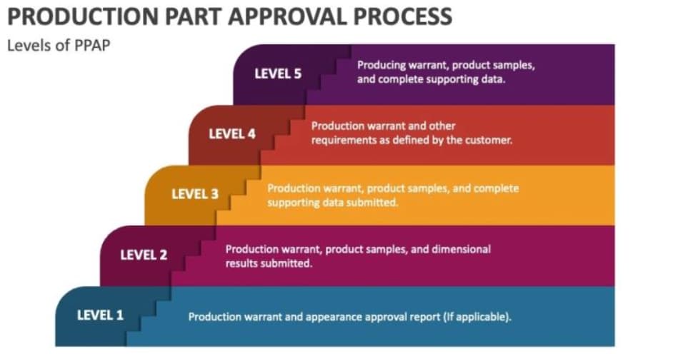
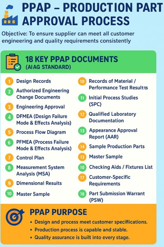
PPAP Submission Best Practices for CNC Machining Suppliers
1. Establish PPAP Readiness Before Quoting
- Review customer-specific requirements early
- Assess capability for required PPAP level
- Factor documentation time into lead time quotes
- Consider PPAP preparation costs in pricing
2. Build Quality Systems That Support PPAP
- Documented process flows for all parts
- Regular PFMEA updates
- Robust control plans with statistical controls
- Calibrated measurement systems with Gage R&R
- Qualified laboratories or in-house capabilities
3. Manage the Submission Timeline
- Begin PPAP preparation during process development
- Allow 2-4 weeks for full Level 3 documentation
- Submit partial packages for review if timeline compressed
- Communicate early if challenges arise
4. Handle Rejection Professionally
- Understand specific rejection reasons
- Implement corrective actions promptly
- Re-submit with clear documentation of changes
- Maintain positive customer communication
5. Leverage PPAP as Competitive Advantage
- Demonstrate capability during quoting phase
- Highlight PPAP expertise in marketing materials
- Use completed PPAPs to reduce future submission burden
- Build reputation for quality and documentation excellence
Common PPAP Challenges and Solutions
Challenge: Insufficient Process Capability
Problem: Cpk values below required minimum (typically 1.33)
Solutions:
- Improve process control before PPAP submission
- Reduce sources of variation
- Implement SPC during production trial runs
- Consider process redesign if fundamentally incapable
Challenge: Dimensional Failures
Problem: Parts out of specification on layout inspection
Solutions:
- Improve measurement systems (calibration, R&R)
- Adjust process parameters to center distribution
- Investigate tooling wear or setup issues
- Consider design tolerance relaxation if functionally acceptable
Challenge: Material Certification Issues
Problem: Missing or incomplete material certifications
Solutions:
- Establish supplier quality requirements early
- Use only certified material suppliers
- Require mill certs with every material delivery
- Maintain material traceability systems
Challenge: Documentation Completeness
Problem: Missing or incorrect PPAP elements
Solutions:
- Use standardized PPAP submission checklists
- Implement document control systems
- Review customer-specific requirements thoroughly
- Conduct internal PPAP audits before submission
Beyond PPAP: Integration with Quality Management
PPAP and IATF 16949
For automotive suppliers, PPAP integrates directly with IATF 16949 requirements:
- Section 8.3.4.3 – Product approval process
- Section 8.5.1 – Control plans
- Section 9.1.1.1 – Monitoring and measurement of manufacturing performance
PPAP and AS9102 (Aerospace)
Aerospace suppliers should note that AS9102 First Article Inspection is similar but distinct from PPAP:
- AS9102 focuses on first article verification
- Different forms and structure than PPAP
- Often required in addition to or instead of PPAP
- More emphasis on balloon drawings and characteristic accountability
Continuous Improvement
PPAP should be viewed as:
- Validation point in new product introduction
- Baseline for ongoing quality monitoring
- Trigger for corrective actions if requirements not met
- Documentation for continuous improvement initiatives
Conclusion
Understanding PPAP Levels 1 through 5 is essential for CNC machining and fabrication suppliers serving quality-conscious industries. While Level 3 remains the default standard for most new production parts, understanding when Level 4 or custom requirements apply can streamline your quality processes and improve customer relationships.
The key to PPAP success lies not in treating it as a documentation burden, but in building robust quality systems that naturally produce the required evidence. When your processes are well-controlled, documented, and capable, PPAP submission becomes a straightforward validation rather than a last-minute scramble.
For suppliers investing in quality management systems, integrating structured approaches such as Forging in Vietnam, further strengthens consistency, traceability, and production control. This capability becomes a competitive advantage, opening doors to automotive, aerospace, medical, and other high-value markets where quality certification is non-negotiable.
About Align Manufacturing
Align Manufacturing provides precision CNC machining and fabrication services with full PPAP capability. We support automotive, aerospace, medical, and industrial customers with comprehensive quality documentation and on-time delivery.
Material Certifications and IMDS Integration for Manufacturing Suppliers
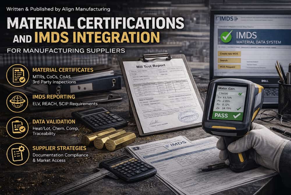
Introduction: The Documentation Imperative
In modern manufacturing supply chains, producing quality parts is no longer sufficient, suppliers must prove quality through comprehensive documentation. Material certifications and the International Material Data System (IMDS) have become gatekeepers to doing business with automotive, aerospace, and medical OEMs. Understanding these requirements isn’t just about compliance; it’s about market access.
This guide demystifies material certification requirements and IMDS integration, providing actionable frameworks for suppliers seeking to meet and exceed their customers expectations.
Understanding Material Certifications
Types of Material Certifications
1. Mill Test Report (MTR) / Mill Certificate
The foundational document from the raw material producer:
| Information Included | Purpose |
| Heat/lot number | Traceability |
| Chemical composition | Alloy verification |
| Mechanical properties | Performance validation |
| Production date | Age-sensitive materials |
| Specification compliance | Standard conformance |
| Mill identification | Source verification |
2. Certificate of Compliance (C of C)

Supplier declaration that material meets specified requirements:
- May be based on MTR review
- Typically issued by distributor or converter
- Less comprehensive than full MTR
3. Certificate of Analysis (C of A)
Detailed chemical composition analysis:
- Element-by-element breakdown
- May include trace element reporting
- Often required for critical applications
4. Third-Party Inspection Certificates
Independent verification by accredited bodies:
- SGS, Bureau Veritas, TÜV, Lloyd’s Register
- Often required for international shipments
- Adds credibility and reduces customer inspection
Industry-Specific Certification Requirements
Automotive (IATF 16949)
| Document | Requirement | Retention |
| Material certifications | Full MTR for all production materials | Production life + 1 year |
| PPAP submissions | PSW with material data | Current + 1 revision |
| IMDS reporting | 100% of supplied materials | Indefinite |
| MSDS/SDS | Current safety data sheets | Current version + 30 years |
| RoHS/REACH | Compliance declarations | Current + 5 years |
Aerospace (AS9100 / AS9120)
| Document | Requirement | Retention |
| Material certifications | Full chemical and mechanical | 40 years minimum |
| Test reports | All testing performed | 40 years minimum |
| Supplier certifications | Approved source documentation | Duration of approval |
| Traceability records | Heat/lot to finished part | 40 years minimum |
| NADCOM / customer special | Process certifications | Per customer requirements |
Medical (ISO 13485)
| Document | Requirement | Retention |
| Biocompatibility | ISO 10993 testing | Device lifetime + 2 years |
| Material certifications | Full traceability | Device lifetime + 2 years |
| Sterilization validation | Gamma, EO, or autoclave data | Device lifetime + 2 years |
| Change control | Material change notifications | Indefinite |
Reading and Validating Mill Test Reports
Key Elements to Verify
1. Specification Alignment
Compare MTR specification to purchase order:
| Purchase Order Spec | MTR Claim | Verification |
| ASTM B16 | ASTM B16 Rev 2021 | Match exact revision |
| C36000 | C36000 | Verify UNS number |
| H02 Temper | H02 | Confirm temper |
| 1/2″ diameter | 0.500″ | Check dimensional |
2. Chemical Composition Analysis
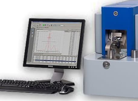
Typical brass composition table from MTR:
| Element | Specification Range | MTR Result | Status |
| Copper (Cu) | 60.0-63.0% | 61.8% | ✓ Accept |
| Lead (Pb) | 2.5-3.7% | 3.1% | ✓ Accept |
| Iron (Fe) | Max 0.35% | 0.12% | ✓ Accept |
| Zinc (Zn) | Remainder | 34.5% | ✓ Accept |
Red Flags:
- Elements outside specification range
- Missing required elements
- “Typical values” instead of actual test results
- No test method cited (e.g., ASTM E415 for spectroscopy)
3. Mechanical Property Verification
| Property | Specification | MTR Result | Tolerance |
| Tensile Strength | 58,000 PSI min | 62,400 PSI | +9% |
| Yield Strength | 45,000 PSI min | 48,200 PSI | +7% |
| Elongation | 25% min | 28% | +12% |
| Hardness | 80-90 HRB | 85 HRB | Mid-range |
4. Traceability Elements
Verify the MTR connects to your material:
- Heat number matches material marking
- Quantity received matches MTR quantity (or is subset)
- Date aligns with production schedule
The IMDS System Explained
What is IMDS?
The International Material Data System is the automotive industry’s global standard for collecting and managing material information:
- Created by: OEM consortium (Audi, BMW, Daimler, EDS, Ford, Opel, Porsche, VW, Volvo)
- Purpose: Track substances of concern; meet ELV, REACH, and other regulations
- Scope: All materials and substances in automotive products
- Current: Over 100,000 users; 400,000+ companies
Regulatory Drivers
| Regulation | Region | IMDS Role |
| ELV Directive 2000/53/EC | EU | Track and report recyclability; banned substance compliance |
| REACH | EU | SCIP database integration; SVHC reporting |
| China Standard GB/T | China | Material substance disclosure |
| K-REACH | Korea | Similar to EU REACH |
| Proposition 65 | California | Substance disclosure for warnings |
| GADSL | Global | Global Automotive Declarable Substance List compliance |
IMDS Structure
The Hierarchy
MDS (Material Data Sheet)
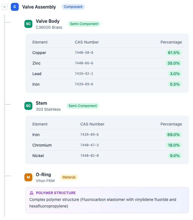
Each Node Contains:
- Identification (part number, name, weight)
- Classification (IMDS code)
- Application (where used in vehicle)
- Substances with CAS numbers and weights
Supplier IMDS Requirements
Who Must Report
| Tier | Responsibility |
| Tier 1 | Report complete assemblies to OEM |
| Tier 2 | Report components to Tier 1 |
| Tier 3+ | Report materials to upstream customers |
| Material Suppliers | Create base material MDSs |
Data Requirements
| Element | Required Information |
| Component name | As on drawing/PBOM |
| Part number | Customer part number |
| Weight | Grams (accurate to 0.001g for small parts) |
| Material classification | IMDS standard codes |
| Substances | All >0.1% by weight (REACH threshold) |
| CAS numbers | Chemical Abstracts Service registry |
| Recyclability | Percentage recyclable content |
Creating IMDS Entries
Step-by-Step Process
Step 1: Gather Information
Required data collection:
- Complete Bill of Materials (BOM)
- Material certifications for all materials
- Weights for each component and material
- Supplier MDS IDs (if available)
- Drawing specifications
Step 2: Request Supplier MDSs
Best practice: Don’t create materials from scratch if supplier already has MDS:
- Request MDS ID and version from material supplier
- Reference in your component MDS
- Ensures consistency and reduces workload
Step 3: Create Component Structure
Example: Brass Valve Assembly
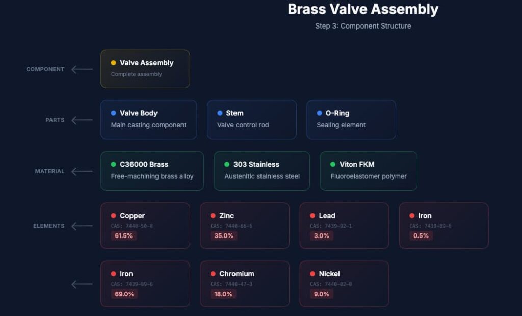
Step 4: Classify and Code
IMDS uses standardized classification codes:
| Code Range | Category |
|---|---|
| 1.x | Steel and iron materials |
| 2.x | Light alloys, cast and wrought alloys |
| 3.x | Heavy metals, cast and wrought alloys |
| 4.x | Special metals |
| 5.x | Polymer materials |
| 6.x | Process polymers |
| 7.x | Other materials and material compounds |
| 8.x | Electronics / electrics |
| 9.x | Fuels and auxiliary means |
Step 5: Validate and Submit
IMDS checks include:
- Weight balance (components sum to parent weight)
- Prohibited substance screening
- Missing information flags
- Customer-specific validation rules
Common IMDS Errors and Solutions
| Error | Cause | Solution |
| Weight mismatch | Components don’t sum to parent | Recalculate and correct weights |
| Jokers | Unknown substances as placeholders | Replace with actual substances or analysis |
| Missing CAS | Substance without CAS number | Look up in IMDS substance list |
| Rejected substance | Banned or restricted material | Find alternative material |
| Application code error | Wrong location classification | Verify against IMDS code list |

Integrating IMDS into Quality Systems
Process Integration Points
1. New Product Introduction (NPI)
- IMDS required before PPAP approval
- Include in APQP timing plan
- Assign IMDS responsibility in project team
2. Supplier Management
- Require IMDS capability in supplier selection
- Include IMDS data in supplier quality agreements
- Audit supplier IMDS processes
3. Engineering Change Control
- Any material change requires IMDS update
- Change board must review IMDS implications
- Customer notification for significant changes
4. Production
- Material lot traceability connects to IMDS
- Ensure actual materials match IMDS declaration
- Control substitution risks
Documentation Control
Required Records
- All submitted MDS IDs and versions
- Supporting material certifications
- Supplier MDS references
- Customer acceptance confirmations
- Change history
Retention Requirements
- Production life + 15 years (automotive typical)
- Verify specific customer requirements
- Some OEMs require 30+ years
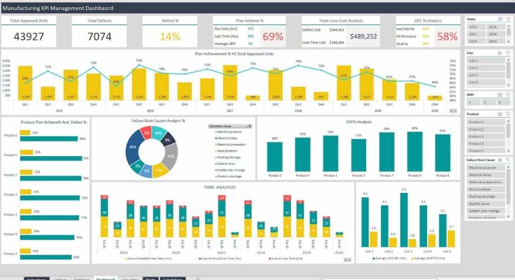
Southeast Asia Implementation
Regional Challenges
Supplier Base Limitations
- Many Tier 2/3 suppliers unfamiliar with IMDS
- Limited access to testing for substance verification
- Language barriers in system navigation
Solutions
- Provide IMDS training to key suppliers
- Offer template MDSs for common materials
- Engage IMDS service providers for support
- Consider English-Chinese-Thai system translations
Local Regulatory Considerations
Thailand Automotive Standards
- TISI (Thai Industrial Standards Institute) alignment with international standards
- Board of Investment (BOI) incentives for EV supply chain participation
- Increasing IMDS requirements from Japanese OEMs with Thai operations
ASEAN Integration
- ASEAN Automotive Federation harmonization efforts
- Cross-border data sharing challenges
- Mutual recognition of certifications developing
Working with Regional OEMs
| OEM | IMDS Requirements | Special Considerations |
| Toyota (Thailand) | Full IMDS required | Japanese material standards |
| Honda (Thailand) | Full IMDS required | Strict change control |
| Ford (Thailand) | Full IMDS required | Aligned with global Ford |
| MG/SAIC (Thailand) | Growing IMDS adoption | Chinese material databases |
| Local Assemblers | Varies | Often less stringent |
Best Practices for Material Documentation
1. Supplier Qualification
Before approving material suppliers:
- Verify certification capability
- Review sample MTRs for completeness
- Confirm IMDS experience (for automotive)
- Audit traceability systems
2. Incoming Inspection
For each material lot:
- Compare MTR to specification
- Verify marking matches paperwork
- Check for certificate authenticity
- Retain samples if required
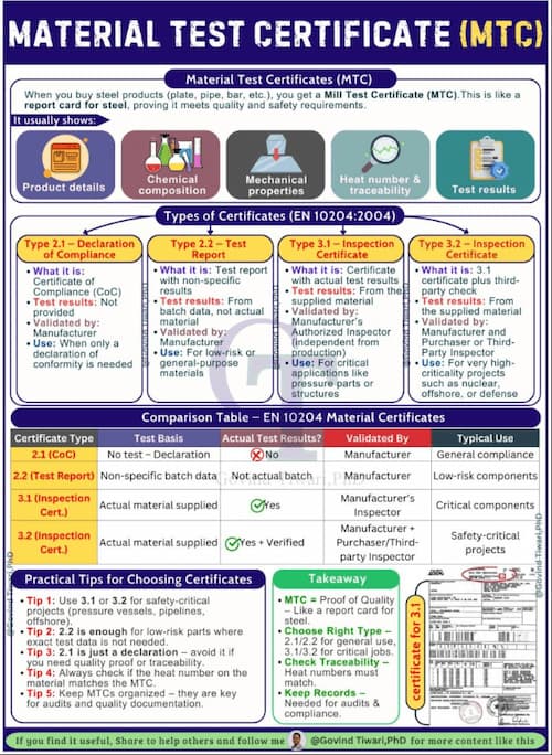
3. Material Traceability
Maintain lot tracking:
- Heat/lot number linked to finished parts
- First-in-first-out (FIFO) stock rotation
- Segregation of different lots
- Computerized tracking systems preferred
4. Customer Communication
Proactive documentation sharing:
- Provide certifications with shipments
- Maintain customer portals for document access
- Notify of any certificate delays
- Offer pre-submission review for critical parts
Conclusion
In today’s documentation-driven manufacturing environment, mastering material certifications and IMDS integration is no longer optional, it is a critical requirement for maintaining compliance, ensuring traceability, and securing long-term customer trust. From validating mill test reports to building accurate IMDS submissions, suppliers that implement structured, repeatable documentation processes position themselves as reliable partners within global supply chains.
For companies operating in highly competitive sectors such as automotive and industrial manufacturing, this level of discipline becomes even more important when supporting processes like forging in Vietnam, where international buyers increasingly expect full transparency, material traceability, and regulatory alignment. By combining strong documentation practices with robust manufacturing capabilities, suppliers can not only meet compliance standards but also unlock greater market access and long-term growth opportunities.
FAQ
Q1: How long must we retain material certifications?
A: Retention periods vary by industry:
- Automotive (IATF 16949): Production life + 1 year (minimum)
- Aerospace (AS9100): 40 years from shipment
- Medical (ISO 13485): Device lifetime + 2 years (often 10-15+ years)
- General Industrial: Typically 7-10 years
Always verify specific customer requirements, which may exceed industry standards.
Q2: Can we use “typical” values from MTRs instead of testing each lot?
A: Generally no for critical applications:
- “Typical” or “nominal” values don’t represent actual lot
- Most automotive and aerospace requires actual test results
- Some non-critical applications may accept typical values with customer approval
- When in doubt, require actual test results
Q3: What if our material supplier won’t provide IMDS data?
A: Options:
- Find alternative supplier with IMDS capability
- Create material yourself from composition data (requires accurate analysis)
- Use IMDS service provider to create entries
- Request customer assistance for critical sole-source materials
Note: Creating materials from scratch requires accurate substance analysis and estimates not acceptable.
Q4: Do we need IMDS for prototype parts?
A: Typically yes:
- Most OEMs require IMDS before PPAP approval
- Prototype phase IMDS often marked “for prototype only”
- Production IMDS must be updated for any material changes
- Early IMDS submission prevents production delays
Q5: How do we handle confidential material formulations?
A: IMDS provides protection mechanisms:
- Pseudo-substances: Hide exact formulation while declaring regulated substances
- Joker system: For complex polymers where exact formula confidential
- Supplier MDS: Reference supplier’s confidential MDS without disclosure
- OEM agreement: Some customers accept offline disclosure for highly confidential materials
Q6: What substances trigger IMDS reporting requirements?
A: Two thresholds:
- REACH SVHC: >0.1% by weight (reportable but not prohibited)
- GADSL: Declarable substances at specified thresholds
- ELV banned: Lead, mercury, cadmium, hexavalent chromium which is prohibited with limited exceptions
Q7: Can we update an IMDS entry after customer acceptance?
A: Yes, through versioning:
- New version supersedes old
- Customer must accept new version
- Always increment version for any change
- Maintain history of all versions
Q8: What’s the penalty for incorrect IMDS data?
A: Consequences can be severe:
- PPAP rejection: Cannot ship production parts
- Stop shipments: Existing business halted until corrected
- Fines: For regulatory non-compliance (REACH, ELV)
- Recall liability: If non-compliant products reach market
- Supplier score impact: Affects future business opportunities
Matching Historic Brass Hardware: CNC Machining for Authentic Reproductions
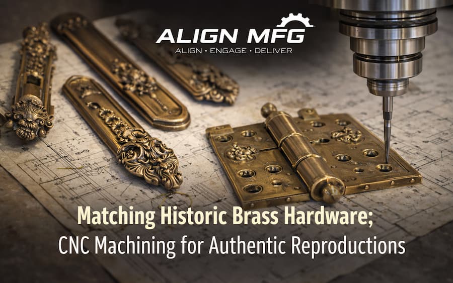
What is CNC Machining?
CNC machining (Computer Numerical Control machining) is a precision manufacturing process where computer-controlled machines remove material from solid metal or plastic to create highly accurate parts based on digital designs. By following programmed toolpaths, CNC machines can replicate complex geometries, tight tolerances, and fine details with consistent repeatability. This makes CNC machining especially valuable for applications such as historic hardware reproduction, where matching the original dimensions, fit, and functionality is critical.
Introduction: When Authenticity Matters
Historic brass hardware, ranging from ornate door handles on Victorian mansions to the simple yet elegant hinges of colonial homes, represents craftsmanship that modern mass production often fails to replicate. For restoration projects, heritage building maintenance, and authentic reproduction manufacturing, the challenge isn’t just creating something that looks similar; it’s achieving dimensional accuracy, material authenticity, and functional equivalence that satisfies preservation standards.
CNC machining has revolutionized historic hardware reproduction, enabling craftspeople and manufacturers to create pieces indistinguishable from originals while meeting modern performance requirements. This guide explores the intersection of historical accuracy and precision manufacturing.
The Heritage Hardware Market
Applications for Historic Reproductions
| Application Sector | Typical Components | Standards Requirements |
| Museum Restoration | Display cases, exhibit hardware | AAM guidelines, reversibility |
| Historic Homes | Door/window hardware, hinges | Secretary of Interior Standards |
| Government Buildings | Legislative chambers, courts | GSA guidelines, Buy American |
| Religious Buildings | Altar hardware, sanctuary fittings | Denominational preservation rules |
| Theater/Film | Set dressing, functional props | Authenticity for period accuracy |
| Luxury Residential | Custom homes seeking period style | Client aesthetic requirements |
| Educational Institutions | Campus heritage buildings | State preservation office standards |
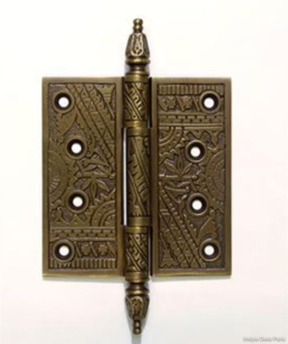
Preservation Standards Overview
Secretary of Interior’s Standards for Rehabilitation
- Standard 2: Preserve historic character
- Standard 6: Repair rather than replace
- Standard 9: Distinguish new work from old (when replacement necessary)
National Park Service Guidelines
- Document existing conditions thoroughly
- Use physical and photographic analysis
- Match materials, design, and finish historically
- Minimum intervention approach
Analyzing Historic Hardware
Documentation and Measurement
Step 1: Photographic Documentation
- High-resolution images from multiple angles
- Macro photography of surface details and patina
- Scale reference in each image
- UV photography to reveal hidden markings
Step 2: Dimensional Analysis
| Measurement Tool | Precision | Application |
| Digital Calipers | ±0.001″ | General dimensions, thickness |
| Micrometers | ±0.0001″ | Precision features, shaft diameters |
| Height Gauges | ±0.001″ | Vertical features, step heights |
| Optical Comparators | ±0.0005″ | Complex profiles, contours |
| 3D Laser Scanners | ±0.002″ | Overall form, organic shapes |
| CT Scanning | ±0.001″ | Internal features, hidden geometry |

Step 3: Material Analysis
Non-Destructive Testing (Preferred)
- XRF (X-Ray Fluorescence): Identifies alloy composition
- Hardness Testing: Confirms temper and alloy type
- Ultrasonic Testing: Detects internal cracks or voids
Destructive Testing (When Sacrifice Acceptable)
- Spectrographic Analysis: Precise elemental composition
- Metallographic Examination: Grain structure, porosity
- Tensile Testing: Mechanical properties
Common Historic Brass Alloys
| Era | Typical Alloy | Characteristics | Modern Equivalent |
| Colonial (1600-1776) | C23000 (85/15) | Reddish color, soft, formable | C23000, C83600 |
| Federal (1776-1830) | C26000 (70/30) | Yellow color, harder | C26000 |
| Victorian (1837-1901) | C28000 (60/40) | Golden color, cast decorative | C28000, C83600 |
| Arts & Crafts (1880-1920) | C27000 (65/35) | Warm color, hand-forged look | C27000 |
| Art Deco (1920-1940) | C36000 (machined) | Bright finish, geometric forms | C36000 |
| Mid-Century (1945-1960) | Various | Often plated, modern alloys | Match original XRF |
CAD Modeling for Historic Hardware
Capturing Organic Forms
Historic hardware often features hand-finished details that don’t translate directly to CAD:
Challenges
- Irregular surfaces from sand casting
- Tool marks from hand finishing
- Worn surfaces from use
- Intentional asymmetry in hand-crafted pieces
Solutions
| Approach | Method | Best For |
| NURBS Surfacing | Control point manipulation | Flowing, organic shapes |
| Sub-D Modeling | Subdivision surfaces | Sculptural, free-form details |
| Reverse Engineering | Scan-to-CAD | Exact reproduction of complex forms |
| Parametric Features | Constraint-based modeling | Geometric, machined components |
| Hybrid Approach | Combine methods | Complex assemblies |
Tolerancing for Function
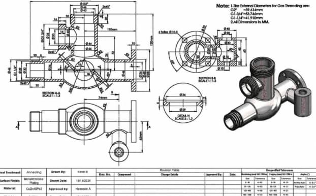
Fit Considerations
| Interface Type | Recommended Tolerance | Notes |
| Pivot/Pin Clearance | +0.002″ to +0.005″ | Allows smooth operation |
| Sliding Fit | +0.001″ to +0.003″ | Smooth, controlled motion |
| Press Fit | -0.001″ to -0.003″ | Permanent assembly |
| Thread Engagement | Class 2B (standard) | General hardware |
| Thread Engagement | Class 3B (precision) | Fine adjustment hardware |
| Backplate Seating | ±0.005″ | Cosmetic only |
Accounting for Patina Buildup Original hardware may have operated with significant patina accumulation. Reproductions should:
- Provide slight additional clearance at wear points
- Specify break-in period in documentation
- Use compatible lubricants (not modern synthetics that alter patina)
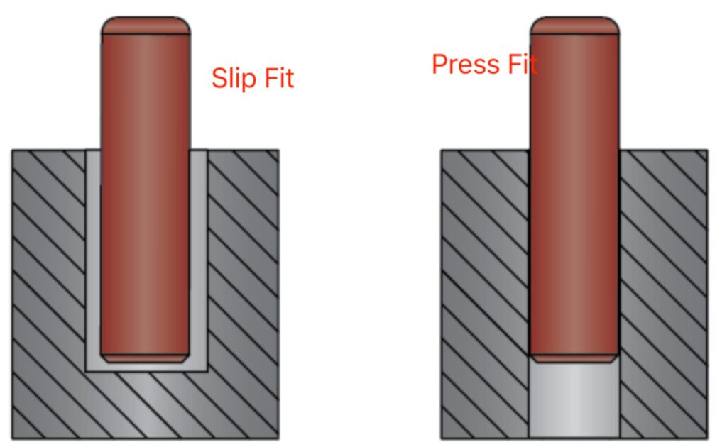
CNC Machining Strategies
Workholding Considerations
Historic hardware often features:
- Thin, delicate sections
- Complex external geometry
- Critical surface finishes
- No flat reference surfaces
Specialized Fixturing
| Component Type | Fixturing Approach |
| Ornate Backplates | Vacuum chuck with custom gasket |
| Curved Handles | Soft-jaw vise with matching contour |
| Delicate Spindles | Collet chuck with minimal clamping |
| Asymmetric Forms | 5-axis positioning with tailstock support |
| Thin Sections | Wax mounting or freeze-fit tooling |
Toolpath Strategies
Roughing
- High-efficiency milling (HEM) for material removal
- Leave 0.010-0.020″ stock for finishing
- Avoid heat buildup that affects temper
Semi-Finishing
- Ball mill passes to prepare for final form
- Maintain consistent stepover for surface quality
- 0.005″ stock remaining
Finishing
| Feature Type | Tool | Strategy |
| Flat Surfaces | Face mill or end mill | Climb milling, fine stepover |
| Contours | Ball end mill | Constant scallop height |
| Sharp Corners | Corner radius or pencil mill | Multiple passes |
| Fine Details | Tapered ball mill | High-speed machining |
| Text/Engraving | Engraving cutter or V-bit | Single pass at full depth |
Surface Finish Considerations
Achieving Period-Appropriate Finishes
| Era/Style | Target Finish | CNC Approach | Post-Process |
| Early Hand-Forged | Hammer marks, irregular | Intentional toolpath variation | Hand distressing |
| Victorian Cast | As-cast texture | Rough pass only, no finish cut | Chemical patina |
| Industrial Era | Machined but not polished | Standard finishing passes | Brushed finish |
| Art Deco | High polish, geometric | Fine finishing, minimal scallops | Polishing, lacquer |
| Arts & Crafts | Hand-rubbed appearance | Directional tool marks preserved | Oil finish |
Tool Marks as Features Some reproductions benefit from visible tool marks that suggest hand crafting:
- Program intentional scallop patterns
- Use larger stepovers in visible areas
- Preserve witness marks from setups
Material Selection for Authenticity
Color Matching
Brass color varies by alloy and finish. Spectrophotometer analysis of originals:
| Alloy | L* (Lightness) | a* (Red-Green) | b* (Yellow-Blue) |
| C23000 | 68-72 | +8 to +12 | +28 to +32 |
| C26000 | 70-74 | +6 to +10 | +32 to +36 |
| C27000 | 72-76 | +4 to +8 | +34 to +38 |
| C28000 | 74-78 | +2 to +6 | +36 to +40 |
Target reproduction finish should match original Lab values within ±2 units
Mechanical Properties
Matching Strength and Work Hardening
Historic hardware may have work-hardened areas from forming:
| Temper | Tensile Strength | Hardness | Application |
| Annealed (O) | 40,000 PSI | 55 HRB | Deep forming, soft details |
| Quarter Hard (H01) | 50,000 PSI | 65 HRB | Moderate forming |
| Half Hard (H02) | 60,000 PSI | 75 HRB | Springs, latches |
| Hard (H04) | 70,000 PSI | 85 HRB | Rigid components |
| Extra Hard (H08) | 80,000 PSI | 95 HRB | Maximum strength |
Historical Accuracy vs. Modern Requirements
Lead Content Considerations
- Pre-2014 hardware: May contain 4-8% lead
- Modern reproductions: Must comply with NSF/ANSI 372 (<0.25% lead)
- Solution: Use silicon brass (C69300) or bismuth brass for machinability
Surface Coatings
- Original: May have mercury gilding, lacquer, or natural patina
- Modern: Lacquer, wax, or controlled patina
- Match appearance while ensuring durability
Finishing and Patination
Mechanical Finishes
| Finish Type | Process | Appearance |
| Brushed | 220-400 grit directional sanding | Subtle lines, matte |
| Satin | Non-woven abrasive, random orbit | Soft sheen, no direction |
| Bright | Polishing to mirror | High reflectivity |
| Antique | Selective darkening, highlight removal | Aged appearance |
| Oil-Rubbed | Dark base with bronze highlights | Deep, rich tones |
Chemical Patination
Traditional Formulas (Use with Safety Precautions)
| Patina Type | Formula | Application |
| Brown/Antique | Ferric nitrate solution | Even application, neutralize |
| Green/Verdigris | Ammonium chloride + copper sulfate | Controlled exposure |
| Black | Liver of sulfur (potassium sulfide) | Dip or brush, seal immediately |
| Red/Orange | Heat + salt solution | Torch coloring |
Modern Equivalents
- Commercial patina solutions (JAX, Birchwood-Casey)
- More consistent, safer handling
- Better documentation for reproducibility
Protective Coatings
| Coating | Durability | Reversibility | Best For |
| Microcrystalline Wax | Moderate | Excellent | Museum pieces, low-use |
| Incralac | Good | Good | Exterior, moderate exposure |
| Clear Powder Coat | Excellent | Poor | High-traffic, functional |
| Lacquer | Fair | Fair | Interior, decorative |
| None (Living Finish) | N/A | N/A | High-use, intentional aging |
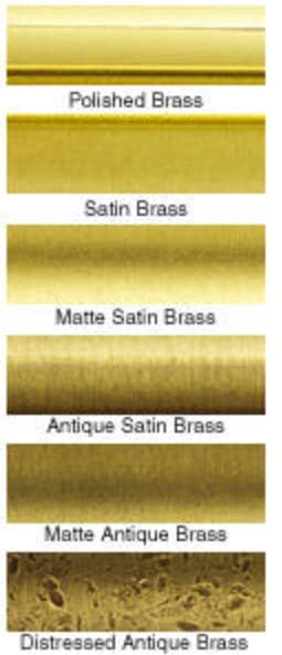
Quality Control for Reproductions
Dimensional Verification
First Article Inspection
- CMM measurement of all critical dimensions
- Surface finish measurement (Ra, Rz)
- Comparison to original artifact or CAD model
- Documentation package for client approval
Statistical Process Control
- Key characteristics monitored in production
- Control charts for critical dimensions
- Go/no-go gauges for rapid inspection
Functional Testing
| Test | Method | Acceptance Criteria |
| Cycle Testing | Automated open/lose cycles | 50,000 cycles minimum |
| Load Testing | Static load application | 3× working load |
| Salt Spray | ASTM B117 | Per specification |
| Hardness | Rockwell or Brinell | Within alloy specification |
| Color Match | Spectrophotometer | ΔE <2.0 from standard |
Documentation Package
Comprehensive reproduction records should include:
- Photographs of original artifact
- Dimensional measurement report
- Material certification
- Finishing process documentation
- Patina formulation
- Care and maintenance instructions
- Certificate of authenticity
Southeast Asia Heritage Projects
Regional Architectural Heritage
Thailand
- Traditional Thai architecture: Ornate gilded hardware
- Colonial influence: Sino-Portuguese mixed styles
- Royal projects: Strict authenticity requirements
Colonial Southeast Asia
- Dutch, British, French architectural hardware
- Mixed cultural influences
- Tropical climate considerations
Sourcing Considerations
Local Material Availability
- Brass rod and bar readily available in Bangkok industrial areas
- Lead-free alloys increasingly available
- Specialty alloys may require import
Export Considerations
- CITES documentation if hardware contains ivory or other restricted materials
- Cultural property clearance for certain antiquities
- Country of origin marking requirements
Conclusion
Reproducing historic brass hardware requires more than visual similarity—it demands precision, material authenticity, and a deep understanding of both traditional craftsmanship and modern manufacturing techniques. CNC machining bridges this gap by enabling accurate replication of complex geometries, controlled tolerances, and consistent surface finishes while maintaining the functional integrity of the original components.
From detailed measurement and material analysis to advanced CAD modeling and finishing processes, each step plays a critical role in achieving results that meet both preservation standards and modern performance requirements. When executed correctly, CNC machining allows manufacturers to deliver components that are visually and functionally aligned with historic originals.
At Align Manufacturing, we specialize in precision-driven reproduction projects, combining engineering expertise with disciplined process control to ensure consistent, high-quality outcomes. With growing capabilities for machining in Vietnam, we are able to support both low-volume custom work and scalable production, offering our partners a reliable solution for complex and detail-sensitive components.
Ultimately, successful historic hardware reproduction is not just about making parts—it’s about preserving craftsmanship, ensuring performance, and delivering long-term value through the right manufacturing strategy.
FAQ
Q1: How accurate should reproduction brass hardware be to the original?
A: Accuracy requirements depend on application:
- Museum display: Exact to 0.001″ where visible
- Functional restoration: Within tolerance for operation
- General reproduction: Visually indistinguishable at 3 feet
- Inspired-by pieces: Captures character, not exact copy
Always document deviations from original when they occur.
Q2: Can we improve the original design of brass hardware while maintaining authenticity?
A: Under Secretary of Interior Standards, improvements must be:
- Reversible without damage to historic fabric
- Distinguishable from original work
- Documented thoroughly
- Approved by appropriate authorities
Common acceptable improvements: Hidden bearings, modern lubricants, stainless steel pins in brass housings.
Q3: What’s the minimum order quantity for custom brass reproduction hardware?
A: CNC machining enables economical small quantities:
- Prototype/single piece: ₫12,250,000–₫49,000,000+ ($500–$2,000+) (high setup cost)
- Small batch (10–50): ₫1,225,000–₫4,900,000 per piece ($50–$200 per piece)
- Medium batch (50–200): ₫735,000–₫2,450,000 per piece ($30–$100 per piece)
- Full production (200+): ₫367,500–₫1,225,000 per piece ($15–$50 per piece)
Costs highly dependent on complexity and finishing requirements.
Q4: How do we handle brass hardware with maker’s marks or logos?
A: Several approaches:
- Exact reproduction: Requires permission from trademark holder
- Generic replacement: Omit marks, reproduce form only
- Documentation: Photograph and preserve original marks separately
- Period-appropriate mark: Use shop mark in period style
When in doubt, consult with a preservation officer or legal counsel.
Q5: Can worn original brass hardware be restored instead of replaced?
A: Restoration is always preferred over replacement when feasible:
- Metal consolidation for deteriorated castings
- Weld repair of cracks or breaks
- Replating worn surfaces
- Replication of missing components only
Restoration requires specialized conservators; CNC machining typically for replacement when restoration is not viable.
Q6: What file formats are needed for CNC machining historic brass hardware?
A: Preferred formats:
- STEP (.stp): Universal CAD exchange
- IGES (.igs): Surface data, older systems
- STL: For 3D printing patterns for casting
- Native CAD: SolidWorks, Fusion 360, etc.
Include:
- 3D solid model
- 2D drawings with tolerances
- Surface finish specifications
- Material callouts
Q7: How do we match the weight/heft of original brass hardware?
A: Weight is a critical authenticity factor:
- Use correct alloy density (brass: 0.308 lb/cu in)
- Match wall thickness exactly
- Account for any hollow sections
- Specify weight tolerance (typically ±5%)
If the original has lead weights (common in sash hardware), replicate with hidden steel or brass to avoid lead content issues.
Q8: What’s the lead time for custom reproduction brass hardware?
A: Typical timeline:
- Documentation/measurement: 1-2 weeks
- CAD modeling: 1-3 weeks
- First article production: 2-4 weeks
- Client approval/revisions: 1-2 weeks
- Production: 2-6 weeks (quantity dependent)
- Finishing/patination: 1-2 weeks
Total: 8-16 weeks typical
Rush service available at premium (30-50% upcharge) for urgent restoration projects.
Internal Auditing and Corrective Action (CAPA) for Machine Shops

Introduction: Building a Quality-First Culture
In the precision-driven world of CNC machining and manufacturing, quality isn’t an inspection step, it’s a continuous process woven throughout operations. Internal auditing and Corrective and Preventive Action (CAPA) form the backbone of proactive quality management, enabling machine shops to identify issues before they reach customers, systematically address root causes, and prevent recurrence.
This comprehensive guide provides machine shop managers, quality engineers, and operators with actionable frameworks for implementing effective internal audit programs and CAPA systems that drive continuous improvement while meeting ISO 9001, IATF 16949, and AS9100 requirements.
Understanding Internal Auditing in Manufacturing
What is an Internal Audit?
An internal audit is a systematic, independent examination of a manufacturing organization’s quality management system (QMS) to determine whether quality activities and related results comply with planned arrangements. Unlike external audits conducted by customers or certification bodies, internal audits are self-directed evaluations designed to drive improvement.
Types of Internal Audits for Machine Shops
| Audit Type | Frequency | Focus Area | Personnel Required |
| System Audits | Annual | Entire QMS against ISO/AS standards | Certified internal auditor |
| Process Audits | Quarterly | Specific manufacturing processes | Process engineer + QA |
| Product Audits | Monthly | Finished parts against specifications | Quality inspector |
| Layered Process Audits (LPA) | Daily/Weekly | Critical control points | Production supervisor |
| Supplier Audits | Annually | Subcontractor capabilities | Purchasing + QA |
| 5S Audits | Weekly | Workplace organization | Production team |
Internal Audit Program Structure
Annual Audit Schedule Example
| Month | Audit Focus | Standard Clause | Auditor |
| January | Management processes | ISO 9001: 4-5 | Quality Manager |
| February | Resource management | ISO 9001: 7 | HR + Operations |
| March | Product realization – Planning | ISO 9001: 8.1 | Engineering |
| April | Purchasing and supplier control | ISO 9001: 8.4 | Purchasing |
| May | Production and service provision | ISO 9001: 8.5 | Production Mgr |
| June | Monitoring and measurement | ISO 9001: 9 | QA Manager |
| July | Corrective action processes | ISO 9001: 10.2 | Quality Manager |
| August | Document and record control | ISO 9001: 7.5 | Document Control |
| September | Calibration and inspection | ISO 9001: 7.1.5 | Metrology Lead |
| October | Customer-related processes | ISO 9001: 8.2 | Sales + QA |
| November | Internal audit process | ISO 9001: 9.2 | Management Rep |
| December | Management review preparation | ISO 9001: 9.3 | Top Management |

Planning Effective Internal Audits
Pre-Audit Preparation
1. Define Audit Scope and Criteria
- Identify processes to be audited
- Reference applicable standards (ISO 9001, IATF 16949, AS9100)
- Review previous audit findings
- Consider customer-specific requirements
2. Select and Prepare the Audit Team
- Auditors must be independent of audited activities
- Minimum requirement: One lead auditor with formal training
- Larger audits: Audit team with defined roles
- Southeast Asia consideration: Ensure language proficiency
3. Develop Audit Checklists
Sample Process Audit Checklist: CNC Turning Operation
| Checkpoint | Evidence Required | Finding | Notes |
| Work instruction available at station? | Posted/current revision | ☐ C ☐ NC ☐ O | |
| Operator trained and certified? | Training records, skill matrix | ☐ C ☐ NC ☐ O | |
| First piece inspection completed? | FAI report, sign-off | ☐ C ☐ NC ☐ O | |
| In-process inspection per control plan? | Inspection records | ☐ C ☐ NC ☐ O | |
| Statistical process control active? | SPC charts, capability data | ☐ C ☐ NC ☐ O | |
| Tooling identified and within life? | Tool life tracking | ☐ C ☐ NC ☐ O | |
| Machine calibration current? | Calibration stickers, certs | ☐ C ☐ NC ☐ O | |
| Preventive maintenance on schedule? | PM records, work orders | ☐ C ☐ NC ☐ O | |
| Nonconforming material identified? | Red tags, quarantine area | ☐ C ☐ NC ☐ O | |
| Corrective actions from previous audits closed? | CAR tracking | ☐ C ☐ NC ☐ O |
C = Conforming, NC = Non-Conforming, O = Observation
Conducting the Audit
Opening Meeting (15-30 minutes)
- Introduce audit team
- Confirm scope and schedule
- Explain audit methodology
- Address confidentiality
On-Site Audit Activities
- Interview Personnel: Ask open-ended questions
- “Walk me through how you set up this job”
- “How do you know when a tool needs changing?”
- “What do you do if you find a defect?”
- Observe Operations: Watch actual work being performed
- Compare to documented procedures
- Note deviations and best practices
- Photograph (with permission) for evidence
- Review Records: Examine objective evidence
- Inspection records, SPC charts
- Training records, certifications
- Maintenance logs, calibration certificates
- Previous audit findings and closures
Closing Meeting (30-45 minutes)
- Present findings (non-conformities and observations)
- Allow auditee to respond and clarify
- Discuss timeline for corrective actions
- Issue draft report within 3-5 business days
Writing Non-Conformity Reports
Non-Conformity Structure (CAR Format)
1. Statement of Non-Conformity Clear, factual description of what was found:
“The CNC milling work instruction WI-045 Rev C specifies measurement of hole diameter at position A after operation OP-20. Review of inspection records for Job #23456 (run date 15 March 2026) showed no diameter measurement recorded, and the operator confirmed this dimension is not routinely checked.”
2. Reference to Standard/Requirement
“This constitutes a non-conformity with ISO 9001:2015 Clause 8.5.1 (c) – ‘the implementation of monitoring and measurement activities at appropriate stages to verify that criteria for control of processes…have been met.'”
3. Classification
- Major: Systemic failure, multiple minor NCs on same clause, potential customer impact
- Minor: Isolated incident, limited impact, easily correctable
4. Evidence References
- Document numbers, revision levels
- Photographs (if applicable)
- Interview notes
- Record samples with dates
The CAPA Process: From Finding to Fix
CAPA vs. Correction
| Aspect | Correction | Corrective Action | Preventive Action |
| Timing | Immediate | Short-term | Long-term |
| Focus | Symptom | Root cause | Potential issues |
| Goal | Fix the problem | Prevent recurrence | Prevent occurrence |
| Example | Rework nonconforming part | Fix broken fixture | Update PM schedule |
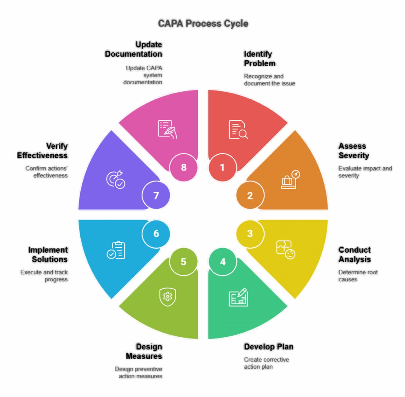
The 8D Problem-Solving Method
Originally developed by Ford Motor Company, 8D is widely used in manufacturing:
D0: Plan
- Define the problem symptom
- Establish emergency response action if needed
- Form the team
D1: Establish the Team
- 4-6 members with process knowledge
- Include operator, engineer, quality representative
- Assign roles: Champion, Team Leader, Recorder, Members
D2: Describe the Problem Use the 5W2H framework:
- What is the problem? (defect type, characteristic)
- Where was it found? (location, machine, shift)
- When did it occur? (date, time, sequence)
- Who is affected? (customer, process, product)
- Why is it a problem? (impact, severity)
- How was it detected? (inspection method, frequency)
- How many were affected? (quantity, percentage)
D3: Develop Interim Containment
- Stop the bleeding: quarantine suspect material
- Sort good from bad
- Implement 100% inspection if necessary
- Document containment effectiveness
D4: Root Cause Analysis Investigate both:
- Escape Point: Why did the defect reach the customer?
- Root Cause: Why did the defect occur?
Use multiple tools:
- 5 Whys: Ask “why” five times to drill down
- Fishbone (Ishikawa): Categories – Man, Machine, Material, Method, Measurement, Environment, Management
- Fault Tree Analysis: Top-down logic analysis
- FMEA: Review for overlooked failure modes
D5: Choose Permanent Corrective Actions
- Address root causes, not symptoms
- Verify actions don’t create new problems
- Define implementation timeline
- Assign responsibility
D6: Implement and Verify
- Execute corrective actions
- Train affected personnel
- Update documents (procedures, work instructions)
- Verify effectiveness with data (30-90 days minimum)
D7: Prevent Recurrence
- Apply lessons learned to similar processes
- Update FMEAs, Control Plans
- Revise training materials
- Communicate across organization
D8: Recognize the Team
- Document and share success
- Reward team members
- Archive for future reference
Root Cause Analysis Tools
The 5 Whys Technique
Example: Dimensional variation on turned parts
| Level | Question | Answer |
| 1 | Why are parts out of tolerance? | Because the cutting tool wears inconsistently |
| 2 | Why does the tool wear inconsistently? | Because feed rates vary between operators |
| 3 | Why do feed rates vary? | Because the parameter sheet is not at the machine |
| 4 | Why isn’t the parameter sheet at the machine? | Because the document control update hasn’t been distributed |
| 5 | Why hasn’t it been distributed? | Because the document change process has no verification step |
Root Cause: Document change process lacks verification of distribution.
| Category | Cause 1 | Cause 2 | Cause 3 |
|---|---|---|---|
| Man | Training | Fatigue | New hire |
| Machine | PM due | Vibration | Spindle |
| Material | Lot var | Mixed | Moisture |
| Method | WI not current | Shortcut | Method var |
| Measurement | Cal due | Gage worn | Method var |
Pareto Analysis
Rank defects by frequency to focus efforts:
| Defect Type | Count | Cumulative % |
| Dimensional | 45 | 45% |
| Surface finish | 30 | 75% |
| Burr | 12 | 87% |
| Contamination | 8 | 95% |
| Other | 5 | 100% |
Focus CAPA efforts on dimensional and surface finish issues first (75% of problems).
CAPA Documentation and Tracking
CAPA Record Requirements
Each CAPA must contain:
- Unique identifier (e.g., CAR-2026-047)
- Date opened and originator
- Problem description (linked to audit finding or NCR)
- Immediate containment actions and dates
- Root cause analysis documentation
- Corrective actions with assigned owners and due dates
- Implementation verification evidence
- Effectiveness verification with metrics
- Closure approval by quality management
- Dates for each milestone
CAPA Tracking Metrics
| Metric | Target | Calculation |
| Open CARs | <10 | Count of active CARs |
| Average age | <30 days | Sum of open days / total CARs |
| On-time closure | >95% | Closed on time / total closed |
| Effectiveness rate | >90% | Effective verifications / total closed |
| Recurrence rate | <5% | Repeated issues / total closed |
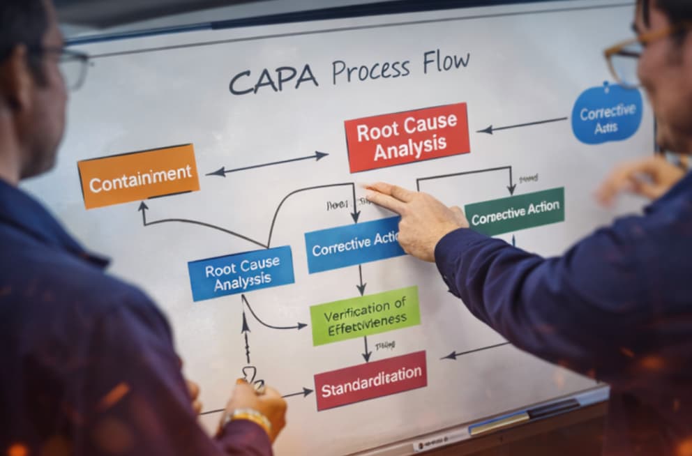
Southeast Asia Implementation Considerations
Cultural Factors
Challenge: Saving Face
- Non-conformities may be perceived as personal criticism
- Root cause analysis may avoid identifying human error
Solutions:
- Frame audits as “process reviews,” not “personnel evaluations”
- Use “we” language: “How can we improve this process?”
- Recognize that honest reporting of problems is encouraged
- Separate the person from the process in all documentation
Challenge: Hierarchical Communication
- Operators may not feel empowered to report issues to auditors
- Corrective actions may need management approval before implementation
Solutions:
- Include supervisors in audit closing meetings
- Establish clear escalation paths
- Empower team-level problem solving within defined limits
- Train management on the importance of rapid response
Language and Documentation
- Provide audit checklists in local language
- Use visual aids (photos, diagrams) to supplement written reports
- Consider bilingual auditors for international customers
- Ensure all personnel understand key quality terms
Regulatory Environment
Thailand Industrial Standards
- TISI (Thai Industrial Standards Institute) requirements for certain products
- Factory Act compliance for safety-related CAPAs
ASEAN Manufacturing Standards
- Harmonizing quality approaches across regional facilities
- Mutual recognition of supplier audits within ASEAN
Audit and CAPA Checklists
Pre-Audit Checklist
☐ Audit scope defined and documented
☐ Audit criteria identified (standards, procedures)
☐ Audit team selected and available
☐ Auditee notified with adequate lead time (1-2 weeks)
☐ Previous audit reports reviewed
☐ Customer complaints and CARs reviewed
☐ Checklists prepared
☐ Opening meeting scheduled
CAPA Implementation Checklist
☐ Root cause verified (not just symptom)
☐ Actions address root cause
☐ Containment verified effective
☐ Documents updated (procedures, WIs, drawings)
☐ Training completed and recorded
☐ Implementation verified within timeframe
☐ Effectiveness metrics defined
☐ Effectiveness verified with data
☐ No negative side effects introduced
☐ Lessons learned communicated
☐ Management approval for closure
FAQ
Q1: How often should we conduct internal audits?
A: ISO 9001 requires audits at planned intervals, typically interpreted as annual coverage of all processes. Best practice for machine shops:
- Entire QMS: Audited at least annually
- Critical processes: Semi-annually or quarterly
- Problem areas: Monthly until stable
- Layered Process Audits: Weekly for high-risk operations
Q2: Can the same person audit a process they work in?
A: No, auditors must be independent of the area being audited to ensure objectivity. However, they can audit other departments or processes. Small shops may need to bring in external auditors or cross-train employees to audit each other’s areas.
Q3: What’s the difference between a correction and a corrective action?
A: A correction fixes the immediate problem (rework a defective part). A corrective action fixes the root cause to prevent recurrence (repair the fixture that caused the defect). ISO 9001 requires corrective actions for non-conformities; corrections alone are insufficient.
Q4: How do we verify the effectiveness of corrective actions?
A: Effectiveness verification requires objective evidence that the problem has been eliminated:
- Statistical data showing defect reduction (minimum 30-90 days)
- No recurrence of the specific issue in subsequent production runs
- Process capability improvements
- Customer complaint reduction
- Audit findings showing sustained compliance
Q5: What if a corrective action doesn’t work?
A: Reopen the CAR and:
- Verify the root cause analysis was correct
- Investigate why the selected action failed
- Apply additional or different corrective actions
- Consider escalation to management for resource support
- Document lessons learned
Q6: How do we prioritize multiple audit findings?
A: Use risk-based prioritization:
- Safety issues: Immediate action required
- Customer impact: High priority, short timelines
- Systemic failures: Address before isolated issues
- Repeat findings: Escalate management attention
- Observations: Address as resources permit
Q7: Can we close a CAR before the effectiveness verification period is complete?
A: No, ISO 9001 requires evidence that corrective actions are effective. Closing before verification is complete violates the standard and risks recurrence. The only exception is if the CAR is reclassified as a preventive action with different timing requirements.
Q8: What’s the role of management review in audit and CAPA?
A: Management review (ISO 9001 Clause 9.3) must include:
- Status of actions from previous audits
- Results of internal and external audits
- Performance of external providers (supplier audits)
- Effectiveness of corrective actions
- Opportunities for improvement
- Resource needs for quality activities
Conclusion
Internal auditing and CAPA are not just compliance requirements, they are essential tools for building a resilient, quality-driven manufacturing operation. When implemented effectively, they transform audits from reactive exercises into proactive systems that continuously identify risks, eliminate root causes, and strengthen process control across the shop floor.
By establishing structured audit programs, clear non-conformity reporting, and disciplined CAPA workflows, machine shops can move beyond firefighting and toward sustainable improvement. The frameworks outlined in this guide, from audit planning and execution to root cause analysis and effectiveness verification, provide a practical roadmap for maintaining compliance while driving measurable operational gains.
For manufacturers operating in competitive regions such as Southeast Asia, the ability to demonstrate strong internal controls and consistent quality performance is a key differentiator. At Align Manufacturing, we support our partners by integrating robust audit and CAPA systems with production best practices, supplier management, and advanced manufacturing capabilities such as investment casting in Thailand, ensuring both process reliability and long-term scalability.
Ultimately, the goal is not just to pass audits, but to build a system where quality is embedded into every step of production which reduces risk, improves efficiency, and delivers consistent value to customers.
Brass Valve Manufacturing: Forging vs. Casting for Durability & Pressure

What Is Forging In Manufacturing?
Forging is a manufacturing process that shapes brass by applying compressive force to heated metal billets or bar stock. Under high pressure, the material is deformed into the desired valve shape, creating a dense structure with aligned grain flow. This results in superior mechanical strength, higher pressure resistance, and improved durability, making forging ideal for demanding and safety-critical applications.
What Is Casting In Manufacturing?
Casting is a manufacturing process where molten brass is poured into a mold and allowed to solidify into the desired shape. This method enables the production of complex geometries and internal passages that would be difficult or costly to machine or forge. While casting is more cost-effective and flexible in design, it typically produces components with lower mechanical strength compared to forged parts.
Introduction: The Critical Choice in Valve Production And Manufacturing
Brass valves are essential components in plumbing, industrial, and marine applications where reliable fluid control under pressure is non-negotiable. The debate between manufacturing methods of forging versus casting, fundamentally determines the valve’s mechanical properties, pressure ratings, durability, and cost. Understanding these differences enables buyers and engineers to make informed decisions that balance performance requirements with budget constraints.
This technical deep-dive compares forging and casting processes for brass valve manufacturing, examining how each method affects material structure, pressure handling, longevity, and economic considerations.
Understanding Manufactured Brass Valve Applications
Common Valve Types
| Valve Type | Primary Application | Pressure Requirements | Typical Manufacturing Method |
| Ball Valves | On/off flow control | 150-600 PSI WOG | Both forging and casting |
| Gate Valves | Isolation services | 125-250 PSI | Primarily casting |
| Globe Valves | Throttling applications | 150-300 PSI | Forging preferred |
| Check Valves | Backflow prevention | 200-600 PSI | Both methods |
| Pressure Relief Valves | Safety applications | 50-400 PSI set pressure | Forging required |
| Marine Valves | Seawater applications | 150-300 PSI | Forging with DZR brass |
Industry Manufacturing Standards
Brass valves must comply with multiple standards depending on application:
- ASTM B62: Standard specification for composition bronze or ounce metal castings
- ASTM B16/B16M: Free-cutting brass rod, bar and shapes for use in screw machines
- NSF/ANSI 61: Drinking water system components: health effects
- NSF/ANSI 372: Drinking water system components: lead content
- MSS SP-110: Ball valves threaded, socket-welding, solder joint, grooved and flared ends
- UL 252: Compressed gas pressure regulators
Forging: The Strength Advantage
The Forging Process for Manufacturing Brass Valves
Forging shapes brass by applying compressive force to heated billets or bar stock. The process fundamentally transforms the material’s internal structure:
- Billet Preparation: Brass rod or bar (typically C36000 free-cutting brass or C37700 forging brass) is cut to weight
- Heating: Billets heated to 1,200-1,400°F (650-760°C) for optimal plasticity
- Forming: Mechanical presses (up to 2,500 tons) or hammers shape the heated brass into valve bodies
- Trimming: Excess material (flash) is removed
- Heat Treatment: Stress relief annealing for complex geometries
- Machining: Precision CNC finishing of seats, threads, and sealing surfaces
Metallurgical Benefits of Forging
Grain Structure Alignment Forging creates directional grain flow that follows the valve’s contours. This grain alignment provides:
- Superior fatigue resistance (3-5× better than castings)
- Higher impact strength
- Improved resistance to stress corrosion cracking
Porosity Elimination Unlike casting, forging eliminates internal porosity through compression:
- Zero gas porosity or shrinkage cavities
- Uniform density throughout the valve body
- Predictable pressure ratings without weak points
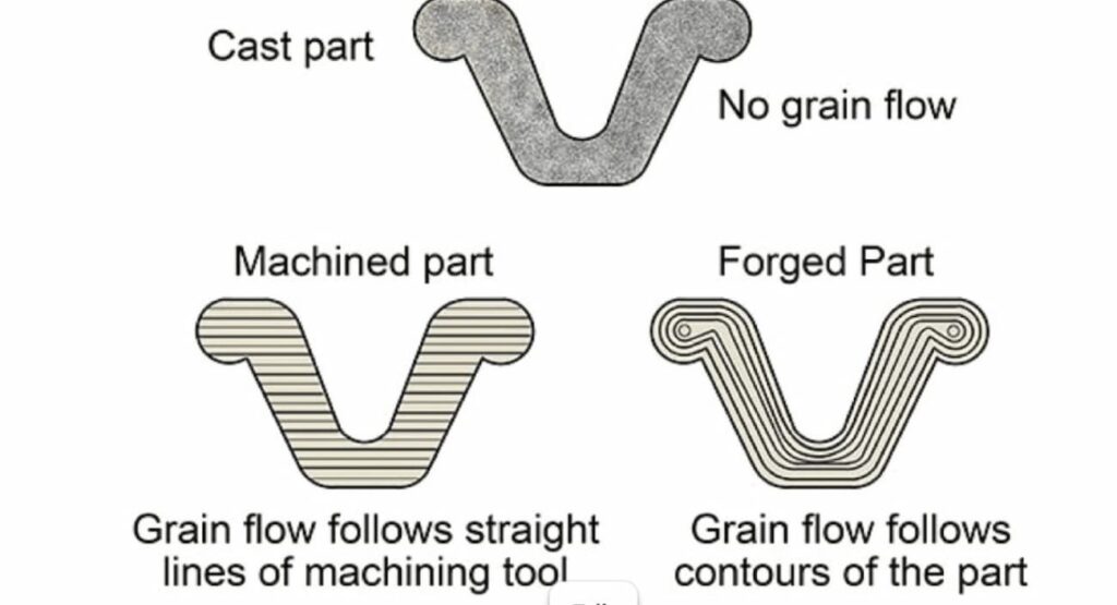
Mechanical Manufacturing Property Improvements
| Property | Forged Brass | Cast Brass | Improvement |
| Tensile Strength | 50,000-60,000 PSI | 30,000-40,000 PSI | +50-67% |
| Yield Strength | 35,000-45,000 PSI | 15,000-20,000 PSI | +100-125% |
| Elongation | 15-25% | 15-20% | Similar |
| Fatigue Strength | 18,000-22,000 PSI | 6,000-10,000 PSI | +120-200% |
| Hardness (Brinell) | 80-100 HB | 60-80 HB | +25-33% |
Pressure Rating Advantages In Manufacturing
Forged brass valves consistently achieve higher working pressure ratings:
- Standard Forged Valves: 600 PSI WOG (Water, Oil, Gas)
- High-Pressure Forged: 1,500+ PSI for hydraulic applications
- Steam Service: 250 PSI saturated steam ratings common
The absence of internal defects means forged valves can safely handle pressure spikes and thermal cycling that would risk casting failure.
When Forging is Essential In Manufacturing
Specify forged brass valves for:
- High-pressure applications (>300 PSI)
- Thermal cycling environments
- Safety-critical systems (gas, steam)
- Corrosive media (saltwater, chemicals)
- Applications requiring maximum longevity
- Aerospace and military specifications
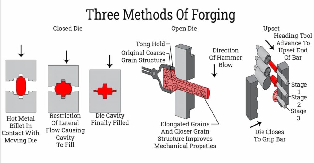
Casting: The Economic and Geometric Advantage
Casting Processes for Manufacturing Brass Valves
Multiple casting methods produce brass valve bodies, each with distinct characteristics:
Sand Casting
- Traditional method using bonded sand molds
- Suitable for large valves (>2 inches)
- Lower tooling costs, rougher surface finish
- Requires more machining allowance
Investment Casting (Lost Wax)
- Wax patterns coated with ceramic shell
- Excellent for complex internal geometries
- Near-net-shape reduces machining
- Best surface finish of casting methods
Die Casting
- High-pressure injection into steel dies
- Fast cycle times for high volumes
- Excellent dimensional repeatability
- Limited to zinc-based alloys primarily
Permanent Mold Casting
- Gravity-fed into reusable metal molds
- Good mechanical properties
- Cost-effective for medium volumes
- Common for 1/2″ to 3″ valve sizes
Economic Advantages of Manufacturing Using Casting
Lower Material Waste
- Near-net-shape reduces machining by 30-50%
- Complex internal passages cast-in, not machined
- Recycled gating and riser material
Tooling Amortization
- Sand casting: Lowest tooling cost ฿180,000–฿720,000 (₫122,500,000–₫490,000,000) ($5,000–$20,000)
- Investment casting: Moderate cost ฿540,000–฿1,800,000 (₫367,500,000–₫1,225,000,000) ($15,000–$50,000)
- Permanent mold: Higher cost ฿900,000–฿3,600,000 (₫612,500,000–₫2,450,000,000) ($25,000–$100,000) but longer life
Volume Economics
| Volume (units/year) | Most Economical Method |
| <1,000 | Sand casting |
| 1,000-10,000 | Investment casting |
| 10,000-50,000 | Permanent mold |
| >50,000 | Die casting (if alloy permits) |
Geometric Flexibility
Casting enables features impossible or prohibitively expensive to forge:
- Complex internal flow passages
- Integral mounting flanges
- Thin-walled sections (down to 1/8″)
- Irregular external shapes
- Multiple cavity configurations
Casting Quality Considerations
Porosity Management
- Proper gating and riser design essential
- Vacuum-assisted casting reduces gas porosity
- Hot isostatic pressing (HIP) can heal internal defects (adds cost)
Wall Thickness Guidelines
- Minimum: 1/8″ (3mm) for small castings
- Recommended: 3/16″ to 1/4″ for pressure retention
- Thick sections (>1/2″) risk shrinkage porosity
Comparative Analysis: Forging vs. Casting
Performance Comparison
| Criteria | Forging | Casting | Winner |
| Pressure Rating | 600+ PSI | 150-300 PSI | Forging |
| Fatigue Life | Excellent | Good | Forging |
| Impact Resistance | Excellent | Moderate | Forging |
| Corrosion Resistance | Better (uniform structure) | Good | Forging |
| Complex Geometry | Limited | Excellent | Casting |
| Internal Passages | Machined only | Cast-in | Casting |
| Surface Finish | Machined surfaces excellent | As-cast surfaces rougher | Forging |
| Dimensional Tolerance | ±0.005″ | ±0.010-0.030″ | Forging |
| Material Utilization | 40-60% | 70-85% | Casting |
| Production Rate | Moderate | High (permanent mold/die) | Casting |
| Tooling Cost | High ฿1,800,000 – ฿7,200,000 (36–180 million VND) ($50,000–$200,000) | Low to Moderate ฿180,000 – ฿3,600,000 (4.5–90 million VND) ($5,000–$100,000) | Casting |
| Unit Cost (low volume) | Higher | Lower | Casting |
| Unit Cost (high volume) | Lower | Higher | Forging |
Cost Analysis at Different Volumes
Scenario: 2-inch brass ball valve
| Volume | Forged Cost | Cast Cost | Difference |
| 100 units | ฿3,060/unit (₫2,082,500/unit) ($85/unit) | ฿1,620/unit (₫1,102,500/unit) ($45/unit) | Casting -47% |
| 1,000 units | ฿1,512/unit (₫1,029,000/unit) ($42/unit) | ฿1,152/unit (₫784,000/unit) ($32/unit) | Casting -24% |
| 10,000 units | ฿1,008/unit (₫686,000/unit) ($28/unit) | ฿936/unit (₫637,000/unit) ($26/unit) | Casting -7% |
| 50,000 units | ฿648/unit (₫441,000/unit) ($18/unit) | ฿864/unit (₫588,000/unit) ($24/unit) | Forging +25% |
Note: Costs include amortised tooling and assume standard C36000 forged brass vs. C84400 cast brass.
Southeast Asia Manufacturing Considerations
Regional Capabilities
Thailand
- Strong forging base with Japanese investment
- C36000 and C37700 brass readily available
- IATF 16949 certified suppliers for automotive valves
- Competitive for 10,000+ unit volumes
China
- Largest global casting capacity
- Sand and investment casting expertise
- Wide range of brass alloys available
- Lowest cost for high volumes (>50,000)
Vietnam
- Growing casting industry
- Cost-competitive for medium volumes
- Improving quality systems
- Good for 5,000-30,000 unit ranges
Quality Assurance Recommendations
When sourcing from Southeast Asia:
- Specify Material Grade: Require mill test certificates for C36000 (forged) or C83600/C84400 (cast)
- Hydrostatic Testing: 100% testing at 1.5× working pressure minimum
- Dimensional Inspection: CMM verification of critical sealing surfaces
- Metallurgical Verification: Grain structure analysis for forgings; porosity testing for castings
- Third-Party Inspection: Engage SGS, Bureau Veritas, or similar for critical applications
Selection Guide: When to Choose Each Manufacturing Method
Choose Forging When:
✓ Working pressure exceeds 300 PSI
✓ Application involves thermal cycling
✓ Safety-critical (gas, steam, hazardous fluids)
✓ Long service life required (>20 years)
✓ High fatigue loading (frequent operation)
✓ Corrosive environment (seawater, chemicals)
✓ Volume exceeds 25,000 units annually
✓ Aerospace, military, or nuclear specifications
Choose Casting When:
✓ Working pressure under 200 PSI
✓ Complex internal geometry required
✓ Weight minimization critical
✓ Volume under 10,000 units annually
✓ Budget constraints significant
✓ Large diameter valves (>3 inches)
✓ Non-critical applications (irrigation, drainage)
✓ Prototyping or product development phase
FAQ
Q1: Can you visually tell the difference between forged and cast brass valves?
A: Sometimes. Forged valves typically have visible parting lines from the forging dies and uniform, machined surfaces. Cast valves may show mold parting lines, slight surface roughness on as-cast areas, and occasionally visible porosity on cut sections. However, finished valves with full machining can be difficult to distinguish visually, though, material testing (spectroscopy, metallography) provides definitive identification.
Q2: Why do manufactured forged valves cost more for small quantities?
A: Forging requires dedicated dies (typically $50,000-$200,000) and larger press equipment. The high fixed costs must be amortized over production volume. Casting, particularly sand casting, has lower tooling costs ($5,000-$20,000), making it more economical for prototypes and low volumes despite higher per-unit material and labor costs.
Q3: Are manufactured forged valves always better than cast valves?
A: Not necessarily. Forged valves offer superior mechanical properties and pressure ratings, but casting provides geometric flexibility and cost advantages for appropriate applications. A properly designed and manufactured cast valve performing within its rated pressure range is perfectly suitable for many applications. The “best” valve depends on the specific service conditions, longevity requirements, and budget constraints.
Q4: Can cast brass valves handle high pressure if they’re thick enough?
A: Wall thickness helps, but doesn’t eliminate casting defects. Thick sections in castings actually increase the risk of shrinkage porosity, which becomes stress concentration points. While heavier cast valves can achieve higher pressure ratings than thin-wall versions, they rarely match forged valve reliability at equivalent pressure levels due to fundamental metallurgical differences in grain structure and defect distribution.
Q5: What’s the lead time difference between manufacturing forged and cast valves?
A: For existing tooled products, forging typically has shorter lead times (4-8 weeks) compared to sand casting (6-10 weeks) because forging is faster per part. However, for new products, forging requires longer tooling development (12-16 weeks) versus sand casting (4-8 weeks). Investment casting falls between these ranges for both production and tooling.
Q6: Are there brass alloys that can only be forged or only be cast during the manufacturing process?
A: Yes. C36000 (free-cutting brass) is designed for machining and forging as it’s rarely cast successfully due to lead content affecting fluidity. Conversely, C83600 (red brass) and C84400 (semired brass) are formulated for casting and don’t forge well due to their tin and zinc content affecting hot workability. C37700 (forging brass) and C35300 (high-leaded brass) bridge both processes.
Q7: How do I verify a supplier’s claimed manufacturing method?
A: Request: (1) Material certifications showing alloy grade, (2) Process documentation or PPAP submission, (3) Metallurgical cross-sections showing grain structure (forged shows directional grain flow; cast shows equiaxed grains with potential porosity), (4) Factory audit if volume justifies, (5) Third-party inspection by accredited bodies like SGS or TÜV for critical applications.
Q8: Can you repair a cracked cast valve by welding?
A: Brass welding is challenging and generally not recommended for pressure-containing components. The heat-affected zone creates metallurgical changes that compromise pressure integrity. Minor surface defects can sometimes be repaired by brazing, but cracked valves should be replaced rather than repaired, especially in pressure or safety-critical applications.
Conclusion
The choice between forging and casting ultimately comes down to balancing performance requirements, design complexity, and production economics. Forging delivers superior strength, pressure resistance, and long-term reliability, making it the preferred solution for safety-critical and high-pressure applications. Casting, on the other hand, provides greater design flexibility and cost efficiency, particularly for complex geometries and lower-volume production.
By understanding how each manufacturing method affects material structure, mechanical properties, and total cost of ownership, engineers and buyers can make more informed decisions aligned with their application needs. The comparative data in this guide highlights that there is no one-size-fits-all solution, only the right process for the right conditions.
For companies sourcing in Southeast Asia, selecting the right manufacturing partner is just as important as selecting the right process. At Align Manufacturing, we work closely with our clients to evaluate application requirements, optimize production methods, and ensure consistent quality across both forging and casting processes. With growing capabilities in areas such as die casting in Vietnam, Thailand and India, alongside precision machining and supplier control, we help deliver reliable, cost-effective solutions tailored to each project.
Ultimately, the goal is not simply to choose between forging or casting, but to implement the most effective manufacturing strategy that ensures performance, quality, and long-term value.
Manufacturing Documentation Control and Material Traceability: A Practical Implementation Guide [2026]
What Manufacturing Documentation Control Actually Means
Manufacturing Documentation control is the systematic management of every record, specification, procedure, and quality document that governs your manufacturing operations. The ISO 9001:2015 standard specifically requires that documented information be controlled when creating and updating, with identification, format, review, and approval requirements clearly defined.
What Is Material Traceability?
Material Traceability is the ability to track raw materials from supplier receipt through production to finished parts and final delivery. It ensures that each component can be linked back to its original material lot, certifications, and processing history, enabling quick identification of issues, effective quality control, and compliance with standards such as ISO 9001. In practice, this follows the “one-up, one-back” principle, where knowing which materials were used in each part and where those parts were ultimately delivered, providing full visibility across the manufacturing process
Introduction
When an aerospace customer calls asking which supplier lot was used in batch 4472 from six months ago, what’s your answer? If it takes more than five minutes to trace that material from finished goods back to the raw material certificate, your documentation control system isn’t working, and you’re only one audit away from a major finding.
Manufacturing documentation control and material traceability aren’t just ISO 9001 requirements. They’re the operational backbone that separates world-class manufacturers from companies living in constant audit anxiety. According to the FDA’s quality system regulation, manufacturers must establish and maintain procedures to ensure that all documents are controlled and that changes are reviewed and approved. For companies serving aerospace, medical device, and automotive industries, the stakes are even higher, AS9100 and IATF 16949 requirements can make or break supplier relationships.
This guide provides a practical framework for implementing documentation control and traceability systems that satisfy auditors, protect your business, and give you confidence when customers ask the tough questions.
The Five Pillars of Manufacturing Documentation Control
| Manufacturing Pillar | Requirements For Manufacturing | Common Failures of Manufacturing | Manufacturing Solutions |
| Availability | Current versions accessible where needed | Outdated work instructions on shop floor | Electronic distribution with automatic updates |
| Protection | Prevent loss, confidentiality breaches | Uncontrolled copies shared via email | Role-based access controls |
| Version Control | Changes tracked with approval history | Multiple versions circulating simultaneously | Single source of truth with revision history |
| Retrievability | Records accessible for audits/investigations | Paper files lost or misfiled | Searchable electronic document management |
| Retention | Meet regulatory and customer requirements | Records destroyed too early | Automated retention scheduling with alerts |
The True Cost of Poor Manufacturing Documentation Control
Poor manufacturing documentation isn’t just an audit headache, it creates measurable business impact:
Rework and scrap: Using outdated specifications costs manufacturers an average of 2-5% of revenue annually
Audit findings: Major non-conformances can delay new business opportunities by 6-12 months
Customer complaints: Inability to demonstrate process control erodes customer confidence
Regulatory action: FDA 483 observations for documentation issues can escalate to warning letters
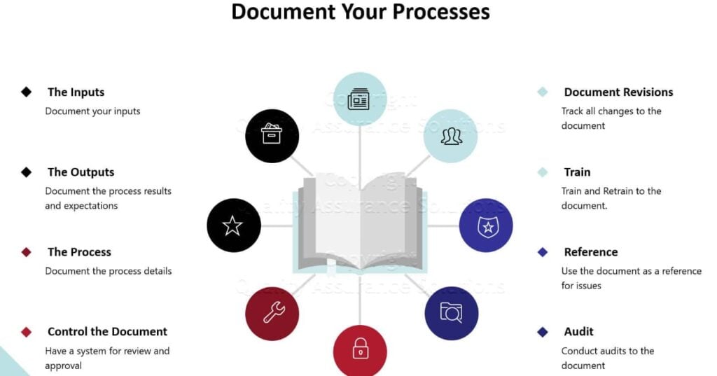
Material Traceability: The One-Up, One-Back Principle
Material traceability tracks the complete journey of raw materials from supplier receipt through production to finished goods shipment. Regulatory frameworks universally require what’s called “one-up, one-back” traceability:
One-back: Know exactly which supplier lot was consumed in each production batch
One-up: Know exactly which customer received each batch of finished goods
This bidirectional linkage enables rapid containment if material defects are discovered and is critical for safety-critical industries where recalls can cost millions.
Essential Manufacturing Traceability Data Elements
Incoming Manufacturing Material Records:
- Supplier name, lot number, certification
- Material grade and specifications
- Certificate of Analysis (CoA) or Certificate of Conformance (CoC)
- Receiving inspection results
- Internal lot assignment and storage location
In-Process Manufacturing Documentation:
- Work order number with material lot linkage
- Machine/workstation identifiers
- Operator identification at each operation
- Critical process parameters (temperature, pressure, time)
- In-process inspection and test results
Finished Manufactured Goods Records:
- Serial numbers or batch numbers
- Complete material genealogy (all lots consumed)
- Final inspection and test results
- Packaging and labeling documentation
- Shipment records with customer destination
Manufactured Material Genealogy Example
Finished Manufactured Good: Valve Assembly SN-2026-04472
| Manufacturing Component | Level 1 | Level 2 |
| Casting | Lot C-2026-0891 (ABC Foundry, Heat 47A) | Material: Brass C36000 Lot M-2026-2341 (MetalCorp) |
| Fasteners | Lot F-2026-556 (FastenRight, Grade 8.8) | – |
| Seals | Lot S-2026-112 (SealTech, Nitrile 70D) | – |
This level of traceability enables complete recall scope identification within minutes, not days.
Standards and Compliance Requirements by Industry
ISO 9001:2015 Foundation
ISO 9001 Clause 7.5 establishes the baseline for documented information control. Key requirements include:
- Identification and description
- Format and media
- Review and approval for adequacy before issue
- Control of changes with version identification

Aerospace: AS9100D Requirements
Aerospace quality management adds stringent requirements beyond ISO 9001:
- First Article Inspection (AS9102): Complete dimensional and documentation verification for initial production runs
- Configuration management: Control of design changes, deviations, and production permits
- Supplier flow-down: Traceability requirements must extend to subcontractors
- Counterfeit prevention: Documentation verifying material authenticity and chain of custody
- AS9100 traceability requirement: Records must be maintained for the specified life of the product plus one year, or as specified by the customer or regulatory authority.

Medical Device: ISO 13485 and FDA 21 CFR Part 820
Medical device manufacturing imposes the strictest traceability requirements:
- Unique Device Identification (UDI): FDA requires unique identifiers on medical devices for post-market surveillance
- Device History Record (DHR): Complete production record for each unit or batch
- Material biocompatibility: Documentation demonstrating material safety for intended use
- Sterilisation validation: Complete records of sterilisation process validation and monitoring
The FDA’s Quality System Regulation states that “each manufacturer shall establish and maintain procedures for identifying products during all stages of receipt, production, distribution, and installation to prevent mixups”.

Automotive: IATF 16949 Requirements
Automotive standards emphasize production part approval and continuous monitoring:
- Production Part Approval Process (PPAP): Comprehensive documentation package including dimensional results, material tests, process capability studies
- Control plans: Detailed documentation of quality controls at each process step
- Customer-specific requirements: OEMs like Toyota, Ford, and BMW impose additional traceability mandates
- Problem solving: Documented 8D or similar processes for containment and corrective action
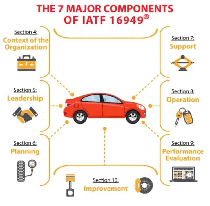
Implementing Documentation Control: A Step-by-Step Framework
Step 1: Document Classification Matrix
Organize documents by type to apply appropriate controls:
| Document Category | Examples | Control Requirements |
| Tier 1: Quality Manual | Policy, scope, management commitment | Controlled distribution, management approval |
| Tier 2: Procedures | Work instructions, SOPs, inspection procedures | Version control, training requirements |
| Tier 3: Records | Inspection reports, production logs | Retention control, authenticity protection |
| Tier 4: External | Customer specs, industry standards, regulations | Current version verification, change monitoring |
Step 2: Version Control Protocol
Implement consistent version identification:
Document Header Example:
Document ID: WI-QC-001
Title: Incoming Material Inspection Procedure
Version: Rev. 04
Effective Date: 2026-02-26
Supersedes: Rev. 03 (2025-11-15)
Approved by: J. Smith, Quality Manager
Page 1 of 12
Critical rules:
Never use “draft,” “preliminary,” or “uncontrolled” in released documents
Include revision history table showing what changed and why
Maintain master document register with current version status
Archive superseded documents but remove from active circulation
Step 3: Change Control Workflow
Every document change must follow a controlled process:
| Stage | Responsible Party | Action | Timeline |
| 1. Request | Any employee | Submit change request with justification | Day 1 |
| 2. Assessment | Document owner | Evaluate impact on operations, training needs | Day 2-3 |
| 3. Draft | Subject matter expert | Prepare revised document | Day 4-7 |
| 4. Review | Affected departments | Technical and operational review | Day 8-10 |
| 5. Approval | Authorized personnel | Final approval per approval matrix | Day 11 |
| 6. Release | Document control | Distribute and communicate changes | Day 12 |
| 7. Training | Supervisors | Train affected personnel on significant changes | Day 13-19 |
| 8. Verify | Quality | Confirm obsolete documents removed from use | Day 20 |
Step 4: Access Control Matrix
Control who can view, edit, and approve based on role:
| Role | View Access | Edit Access | Approve Authority |
| Production staff | Current work instructions only | No | No |
| Quality inspectors | All quality documents | Inspection records only | No |
| Department supervisors | Department documents | Draft changes | Department procedures |
| Quality manager | All documents | All documents | Quality system documents |
| General manager | All documents | Policy documents | All documents |
Building Material Traceability Systems
Receiving: The Traceability Foundation
Required documentation at receipt:
- Supplier packing slip with lot numbers
- Certificate of Analysis (CoA) or Certificate of Conformance (CoC)
- Material test reports (chemical composition, mechanical properties)
- Receiving inspection checklist completion
- Photographs of material condition and labeling
Best practice: Assign internal lot numbers immediately upon receipt, even when suppliers provide lot numbers. This prevents confusion when:
- Multiple suppliers use similar numbering schemes
- Supplier lot numbers are ambiguous or missing
- Material from different supplier lots is blended
In-Process Traceability Methods
Paper-based approach (smaller operations):
- Work order traveler with material lot fields
- Operator signatures at each operation
- Inspection stamps or stickers
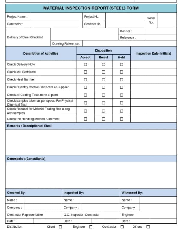
Electronic approach (larger operations):
- Barcode scanning at each operation
- RFID tags for automatic tracking
- MES integration for real-time genealogy
Critical requirement: At every operation, document which material lots were consumed and which finished goods lots were produced.
Finished Goods Identification Strategies
| Serialization Method | Format | Best For |
| Sequential | 0001, 0002, 0003… | Low volume, high value |
| Date-coded | 260226-001 (YYMMDD-XXX) | Time-sensitive traceability |
| Smart codes | PN-LOC-YY-XXXX (Product-Location-Year-Sequence) | Complex product families |
| Random unique | 8A4F92B7… | High security requirements |
Technology Solutions: From Paper to Digital
Electronic Document Management Systems (EDMS)
Modern EDMS platforms provide capabilities that paper systems cannot match:
| Feature | Business Benefit |
| Automatic version control | Prevents use of outdated documents |
| Electronic signatures | Speeds approvals, provides audit trails |
| Role-based access | Protects confidential information |
| Full-text search | Finds documents in seconds, not hours |
| Integration with ERP/MES | Links documents to transactions |
| Automated workflows | Routes documents for review and approval |
Leading EDMS providers: MasterControl, EtQ, Intellect, Documentum
Manufacturing Execution Systems (MES)
MES platforms bridge ERP and shop floor operations:
- Electronic work instructions with embedded quality checks
- Real-time production tracking with automatic material genealogy
- Quality enforcement (cannot proceed past incomplete inspections)
- Machine integration for automatic data collection
Benefit: Eliminates paper travelers, reduces transcription errors by 90%+, enables instant traceability queries.
ERP-Integrated Traceability
Enterprise Resource Planning systems with quality modules offer:
- Lot tracking from purchase order through shipment
- Quarantine management for inspection hold material
- Automatic traceability reports for customer or regulatory requests
- Supplier scorecards based on quality and delivery performance
Document Retention: How Long and Why
Retention Period Guidelines by Document Type
| Document Category | ISO 9001 | Aerospace | Medical Device | Automotive |
| Quality manual/procedures | Product life + 1 year | Product life + 1 year | Product life + 2 years | Product life + 1 year |
| Inspection records | Product life + 1 year | 10+ years | Product life + 2 years | 15 years |
| Material certifications | Product life + 1 year | Permanent | Permanent | Product life + 1 year |
| Calibration records | Current + 2 cycles | Current + 2 cycles | Current + 2 cycles | Current + 2 cycles |
| Training records | Employment + 3 years | Employment + 3 years | Employment period | Employment + 3 years |
| Internal audits | 3 years | 3 years | 3 years | 3 years |
Critical note: Always check customer-specific requirements, which may exceed regulatory minimums. Aerospace prime contractors often require 10-20 year retention for flight-critical components.
Conclusion
Selecting the optimal brass alloy for machining requires balancing machinability, corrosion resistance, regulatory compliance, and cost. C360 remains the production champion for general applications where lead content poses no concerns. C464 serves critical marine and heat transfer applications despite machining challenges. C485 bridges the gap between performance and environmental compliance.
By understanding these alloys’ distinct properties and following the machining guidelines outlined above, manufacturing engineers and buyers can optimize both part performance and production economics. The data-driven comparisons in this guide provide the foundation for informed material selection decisions.
For complex applications or high-volume production runs, we at Align Manufacturing work closely with our customers to ensure the right material and process decisions are made from the start. Leveraging our experience across precision machining operations and automation in the casting process, we focus on material selection, supplier control, and production discipline to deliver consistent and reliable results across a wide range of industries.
The small time investment in proper alloy selection pays dividends through improved quality, reduced scrap, and lower total manufacturing costs which is an approach we apply at Align Manufacturing to help our partners achieve better performance and long-term production efficiency.
FAQ: Documentation Control and Traceability
Q1: How long must we keep manufacturing records?
Minimum: Product life plus one year per ISO 9001. Aerospace and medical devices often require 7-10 years or permanent retention. Always verify customer-specific requirements.
Q2: Can we use electronic signatures For Manufacturing Documentation?
Yes, if your system meets regulatory requirements for electronic records (21 CFR Part 11 for medical devices, EU Annex 11 for pharmaceuticals). Must include audit trails, access controls, and signature authentication.
Q3: What if a supplier doesn’t provide lot numbers?
Assign internal receiving lot numbers and require suppliers to reference your lot numbers on their documentation. For critical materials, only use suppliers who can meet your traceability requirements.
Q4: How do we trace manufacturing material when multiple lots are blended?
Create a new lot number for the blend and document all contributing lots with quantities. Maintain blending calculations and ratios in your records.
Q5: What’s the difference between lot traceability and serialization?
Lot traceability tracks by batch (one record per lot). Serialization tracks individual units (unique ID per part). Serialization provides more granular traceability but requires more sophisticated systems.
Q6: Do we need traceability for all materials or just critical ones?
Regulations require traceability for materials affecting product conformity. Many companies extend to all materials for complete process control and to simplify systems.
Q7: How can small manufacturers afford traceability systems?
Start with paper travelers and lot tags. Implement barcode scanning as volume grows. Cloud-based MES systems like Tulip or ProShop offer affordable entry points starting at $500-1000/month.
Q8: What happens if we discover a traceability gap during an audit?
Immediate containment (hold suspect material), root cause analysis, corrective action implementation, and evidence of effectiveness. Transparent communication with auditors is essential.
Q9: Can traceability requirements be flown down to subcontractors?
Yes, and they should be. Include documentation and traceability requirements in purchase orders and audit subcontractors to verify compliance.
Q10: How do we maintain traceability during rework?
Document rework operations separately, linking back to original production records. Include rework rationale, process used, inspection results, and final disposition.