
Tempering Steel: Definition, Process, Temperatures, Microstructure, Types
Tempering steel is the controlled reheating of quenched steel to a temperature below the lower critical point, typically between 150 to 700 °C, followed by a soak and a controlled cool. The goal is simple yet profound. reduce brittleness, relieve internal stresses, and tune the balance between hardness and toughness so the steel can perform reliably in service.
From the straw and blue tempering colors used by ancient swordsmiths to the multi zone vacuum and atmosphere furnaces used in industry today, the principle has remained the same. take an overly hard and brittle microstructure and make it durable. At Align MFG, we apply these same fundamentals across our manufacturing hubs in Thailand, Vietnam, and India, using modern process control to deliver consistent performance in industrial parts.
In this first half of the article, you will learn what tempering is, why manufacturers rely on it, how the process works step by step, what happens to the steel microstructure, the major types of tempering with their best use cases, and how temperature relates to properties. The second half will cover applications by industry, advantages and limitations, comparisons to other heat treatments, quality control, troubleshooting, safety, and future trends.
What Is Tempering Steel
Tempering is a heat treatment performed after quenching that reheats steel to a temperature below the austenite formation threshold in order to reduce brittleness, stabilize the microstructure, and achieve a targeted balance of hardness and toughness. The process is essential because as quenched martensitic steel is hard but prone to cracking under impact or cyclic loads. Tempering moderates that brittleness without discarding the beneficial hardness entirely.
Historically, craft workers used tempering colors on polished steel surfaces to estimate temperature. straw at about 200 °C, brown near 240 to 260 °C, purple near 280 to 300 °C, and blue near 300 to 320 °C. Modern manufacturing uses thermocouples, programmed recipes, and controlled atmospheres, but the principle of precise temperature control remains the foundation.
Why Temper Steel in Manufacturing
Tempering provides a set of practical, high value benefits that align with real world performance needs.
- It increases toughness and ductility so parts can absorb energy without catastrophic fracture.
- It relieves internal stresses from quenching, which reduces the risk of cracking and distortion.
- It stabilizes dimensions, which improves fit and tolerance control during finishing and assembly.
- It tunes hardness and wear resistance to the working conditions of the part.
- In certain alloy systems, it enables secondary hardening for improved hot strength and wear resistance at higher temper temperatures.
Without tempering, quenched steels remain vulnerable to impact failure, quench cracking, and premature fatigue. With tempering, the result is a more forgiving and predictable material that can endure service loads with confidence.
A helpful analogy is to think of quenching as an intense workout that leaves the material tense and strained. Tempering is the active recovery session that relaxes the microstructure and brings performance into an optimal range.
How Tempering Works. Heating, Dwelling, Cooling
Tempering follows a three stage sequence that can be summarized as Heating followed by Dwelling followed by Cooling. Each stage is controlled to achieve specific metallurgical outcomes.
Step 1. Heating
- Target range. 150 to 700 °C depending on steel grade, carbon content, alloying elements, and property targets.
- Selection logic. Lower temperatures favor retention of higher hardness but limited toughness increase. Higher temperatures increase toughness and ductility at the expense of hardness.
- Timing. For most steels, tempering should occur soon after quenching to reduce the risk of delayed cracking.
- Rate control. Heat rates are managed to avoid steep thermal gradients. Larger or more complex parts often use staged preheats to ensure even temperature rise.
- Atmosphere. To minimize scale and decarburization, parts are tempered in vacuum, inert gas, or controlled atmospheres. Choice depends on material, surface finish requirements, and furnace capability.
Step 2. Dwelling
- Purpose. The soak allows carbon to diffuse, carbides to precipitate, and residual stresses to relax. This is where most of the property tuning occurs.
- Typical soak time. A common starting rule is about one hour per inch of section thickness, adjusted to alloy and specification. Thin sections or highly conductive parts may require shorter times.
- Uniformity. Proper racking and spacing promote uniform temperature and reduce shadowing or cold spots inside the furnace.
Step 3. Cooling
- Method. Most tempering cycles end with air cooling to ambient temperature.
- Special cases. Certain alloy steels are susceptible to temper embrittlement if held or cooled slowly through specific temperature bands. In such cases, faster cooling from the tempering temperature can be beneficial.
- Surface control. Atmosphere management continues to matter during cool down. In many operations, parts remain under protective gas during the initial cool to minimize oxidation.
Microstructural Changes During Tempering
Tempering transforms an unstable, stressed microstructure into a stable and tougher one through diffusion driven processes. The main actors are martensite, retained austenite, ferrite, and carbides.
Martensite Decomposition and Carbon Diffusion
Quenching creates a supersaturated martensite with a distorted lattice and very high dislocation density. During tempering, carbon atoms diffuse and reduce lattice distortion, which lowers internal stress and brittleness. At low tempering temperatures, very fine transition carbides precipitate within the martensite. As temperature rises, these transition carbides evolve and coarsen, and the microstructure gradually approaches tempered martensite, which is ferritic matrix containing uniformly distributed carbides.
Retained Austenite Transformation
Some quench conditions and alloy chemistries leave a fraction of austenite untransformed at room temperature. Tempering destabilizes retained austenite, which can transform during the cycle or in a subsequent temper. In tool steels and high alloy grades, a double temper is often used to transform retained austenite more completely and then refine the resultant structure. In critical applications, a cryogenic step before tempering can reduce retained austenite content further.
Precipitation and Secondary Hardening
Alloyed steels that contain elements like chromium, molybdenum, vanadium, and tungsten can show secondary hardening when tempered at higher temperatures. In this regime, very fine alloy carbides precipitate, which can raise hardness after an initial drop. This is advantageous for hot work and high speed tool steels where wear resistance and hot strength are needed at elevated service temperatures.
Relating these transformations to core materials science, the iron carbon phase diagram defines the austenite stability boundaries, while time temperature transformation and continuous cooling transformation curves help predict what happens during quench and temper cycles. In practice, tempering is about guiding diffusion and precipitation to a target end state.
Types of Tempering and When to Use Each
Tempering strategies vary by temperature, number of cycles, and method of heat input. Selection depends on alloy, section size, part geometry, and the required property profile.
Low Temperature Tempering. 150 to 250 °C
- Purpose. Stress relief and modest toughness increase while retaining high hardness.
- Typical uses. Cutting tools, bearings, gauge blocks, and parts that need maximum wear resistance with limited impact loading.
- Outcomes. Internal stress reduction, slight decrease in hardness, and controlled microstructural stabilization.
Medium Temperature Tempering. 300 to 450 °C
- Purpose. Balanced hardness and toughness for parts that see both wear and dynamic loading.
- Typical uses. Springs, wear plates, gears that need a compromise between surface durability and core toughness.
- Outcomes. More significant toughness improvement with a moderate drop in hardness relative to low temperature tempering.
High Temperature Tempering. 450 to 700 °C
- Purpose. Maximum toughness and ductility with substantial stress relief and dimensional stability.
- Typical uses. Structural components, heavy duty shafts, automotive and industrial machinery parts where impact and fatigue resistance dominate.
- Outcomes. Lower hardness, high toughness, stable dimensions, and improved machinability when post temper finishing is required.
Double Tempering
- Purpose. Reduce retained austenite content, homogenize carbide distribution, and stabilize the microstructure for demanding service.
- Typical uses. Cold work and hot work tool steels such as D2 and H13, and high strength alloy steels for aerospace grade parts.
- Outcomes. Improved dimensional stability, more consistent hardness through section, better fatigue performance.
Precipitation Tempering and Secondary Hardening
- Purpose. Exploit alloy carbide precipitation to regain hardness at higher temper temperatures.
- Typical uses. High speed steels and Cr Mo V tool steels that must retain wear resistance at elevated temperatures.
- Outcomes. A hardness valley followed by a hardness rise at higher temper ranges, along with improved hot strength.
Subcritical Tempering versus Intercritical Treatments
- Conventional tempering is subcritical, meaning always below the Ac1 temperature so that no austenite forms. This is the standard approach for quench and temper processes.
- Intercritical treatments are specialized cycles that briefly enter the austenite formation range for certain alloy designs. These are not typical for standard tempering and should be used only with a validated metallurgical rationale.
Induction Tempering and Flash Tempering
- Induction tempering uses localized heating for rapid and targeted tempering of selective areas such as gear teeth or welded regions. The short cycle time and precision of heat placement can minimize distortion and increase throughput.
- Flash tempering is an ultra rapid temper used primarily on very thin sections or surface hardened cases. It relies on brief exposure to the target temperature with immediate cool down.
Temperature and Property Relationships
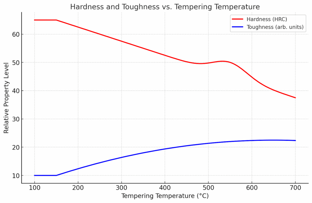
Tempering temperature is the most powerful lever for tuning hardness, toughness, ductility, and wear resistance. As a general rule, higher tempering temperatures give more toughness and ductility with lower hardness, while lower tempering temperatures preserve hardness at the cost of brittleness. Some alloy systems show secondary hardening at higher temperatures due to fine alloy carbide precipitation.
Tempering Colors as Practical Guides
Although not a replacement for thermocouples and calibrated control, tempering colors on a polished surface provide a quick visual cue in workshop settings.
- Pale straw. about 200 °C
- Dark straw to brown. about 230 to 260 °C
- Purple. about 280 to 300 °C
- Blue. about 300 to 320 °C
- Gray. above about 330 °C
These colors depend on surface condition, atmosphere, and lighting. They are best considered supplemental indicators rather than primary controls.
Representative Property Trends by Tempering Range
The following tables summarize typical relationships between tempering temperature and mechanical outcomes. Values are representative and depend on chemistry, prior austenitization, quench severity, section size, and temper time.
Table 1. Tempering temperature and typical outcomes for common steels
| Steel grade | Tempering temperature °C | Typical hardness HRC | Toughness trend | Wear resistance | Notes |
| 1045 medium carbon | 200 to 250 | 50 to 55 | Slight increase | High | Stress relief and minor softening |
| 1045 medium carbon | 400 to 500 | 35 to 45 | Significant increase | Moderate | Balanced properties for shafts and pins |
| 1045 medium carbon | 600 to 650 | 20 to 30 | High | Low | Maximum ductility and machinability |
| Steel grade | Tempering temperature °C | Typical hardness HRC | Toughness trend | Wear resistance | Notes |
| 4140 alloy | 200 to 250 | 52 to 58 | Moderate increase | High | Useful for wear critical parts with limited impact |
| 4140 alloy | 400 to 500 | 38 to 48 | Large increase | Moderate | Common range for gears and shafts |
| 4140 alloy | 550 to 650 | 28 to 35 | High | Lower | Suitable for structural duties with impact loads |
| Steel grade | Tempering temperature °C | Typical hardness HRC | Toughness trend | Wear resistance | Notes |
| D2 tool steel | 150 to 250 | 58 to 62 | Small increase | Very high | First temper in double temper practice |
| D2 tool steel | 450 to 550 | 56 to 60 | Moderate | Very high | Secondary hardening region for wear tools |
| D2 tool steel | 575 to 600 | 54 to 57 | Moderate to high | High | Often used for dies needing toughness and wear |
| Steel grade | Tempering temperature °C | Typical hardness HRC | Toughness trend | Wear resistance | Notes |
| H13 hot work | 500 to 600 | 46 to 52 | Moderate to high | High at temperature | Typical double temper range |
| H13 hot work | 600 to 650 | 44 to 48 | High | Moderate | Improves thermal fatigue resistance |
| H13 hot work | 650 to 700 | 40 to 44 | High | Moderate to low | Maximizes toughness and stability |
| Steel grade | Tempering temperature °C | Typical hardness HRC | Toughness trend | Wear resistance | Notes |
| M2 high speed | 200 to 300 | 63 to 66 | Small | Very high | Retains high hardness at low temper |
| M2 high speed | 500 to 560 | 60 to 64 | Moderate | Very high | Secondary hardening plateau |
| M2 high speed | 560 to 600 | 58 to 62 | Moderate | High | Used for hot strength and wear at temperature |
Key patterns to note
- Medium carbon steels such as 1045 show a steady hardness decrease with increasing temper temperature and a consistent rise in toughness.
- Alloy steels such as 4140 offer broad temper windows that can be tuned for balanced properties. This is why they are common in shafts, gears, and fasteners.
- Cold work tool steels such as D2 show strong wear resistance across a wide temper range, with a beneficial secondary hardening response in the higher temper region.
- Hot work and high speed steels such as H13 and M2 leverage secondary hardening to sustain hardness at elevated operating temperatures.
Practical Guidance for Selecting Tempering Temperatures
- Start with the alloy data sheet and recommended temper ranges for the intended application. Target the lowest temperature that meets toughness and stability requirements if wear resistance is critical. Choose higher temper temperatures if impact and fatigue performance dominate.
- Consider double temper cycles for tool steels and high hardenability alloys. The first temper reduces brittleness and transforms some retained austenite. The second temper homogenizes the microstructure and stabilizes properties.
- Avoid dwelling in temperature ranges known to produce temper embrittlement for susceptible steels. If the application or alloy is at risk, plan for faster cooling from the temper.
- Use witness samples and hardness checks to verify time and temperature choices before full scale production. Document the relationship between hardness and temper temperature for your specific material lot and section size.
Industrial Applications and Case Examples
Tempering tailors steel to the in service loads and environments of five core sectors we support at Align MFG. Oil and Gas, Railway, Construction, Truck and Trailer, and Industrial equipment. By selecting the right tempering window and cycle, we trade just enough hardness for toughness, dimensional stability, and fatigue strength to match each component’s duty.
Oil and Gas
These components see high loads, pressure cycling, abrasion, and sometimes corrosive media. Tempering choices prioritize strength with high impact toughness and tight hardness control across sections.
- Downhole tools such as drill collars, jars, and subs
Typical approach. quench and temper 4140, 4145H, or 4330V mod at 500 to 650 °C to achieve high toughness with controlled hardness through section
- Wellhead bodies, flanges, and valve internals
Typical approach. quench and temper 8630M or 4130 at 500 to 650 °C for fracture resistance. For martensitic stainless such as 410 or 420, temper at 200 to 350 °C to balance hardness and corrosion performance
- Pressure control connectors and adapters
Typical approach. high toughness temper on 8630M at 550 to 650 °C to mitigate crack initiation at stress concentrations
Railway
Railway hardware demands long life under bending and impact with strict dimensional control. The temper strategy aims at high fatigue strength and impact toughness.
- Axles and large shafts
Typical approach. quench and temper 42CrMo4 or 4140 at 500 to 650 °C for a tough core with good surface durability
- Couplers, yokes, and draft gear components
Typical approach. quench and temper 8630 or 4330 at 450 to 600 °C for strength with reliable notch toughness
- Bogie links, brake levers, and brackets
Typical approach. quench and temper medium carbon steels such as 1045 to 1050 at 400 to 550 °C to balance wear and impact resistance
Construction
Equipment faces abrasive wear, shock loading, and outdoor exposure. Tempering balances wear resistance with the toughness needed to avoid brittle failures in the field.
- Ground engaging tools such as bucket teeth and cutting edges
Typical approach. quench and temper boron alloy steels such as 10B38 or 15B30 at 200 to 450 °C depending on the hardness target and wear requirement
- Hydraulic cylinder rods and pins
Typical approach. quench and temper 1045 or 4140 at 400 to 600 °C for stable dimensions, good toughness, and machinability after temper
- High strength anchor rods and heavy fasteners
Typical approach. quench and temper 4140 at 450 to 600 °C to meet strength class while preserving ductility for installation
Truck and Trailer
Components need endurance under vibration, road shock, and varying loads. Tempering targets fatigue strength and reliable toughness.
- Axles, spindles, and hubs
Typical approach. quench and temper 4140 or 4340 at 500 to 650 °C for high toughness and dimensional stability
- Leaf springs and suspension links
Typical approach. quench and temper 5160 or Si Cr spring steels at 350 to 500 °C to achieve high yield strength with endurance under cyclic loading
- Kingpins, drawbar eyes, and fifth wheel plates
Typical approach. quench and temper 4140 at 450 to 600 °C for impact resistance and wear durability
- Wheel studs and U bolts
Typical approach. case harden medium carbon boron steels such as 10B21, then temper subcritically at 200 to 300 °C to stabilize the case and relieve stresses
Industrial
This covers general machinery, power transmission, and plant equipment with many balance of property requirements. Tempering is the lever that tunes hardness, wear, and fatigue.
- Gears, pinions, and shafts
Typical approach. quench and temper 4140 or 4340 at 400 to 550 °C for a balanced hardness with strong tooth root toughness
- Sprockets, couplings, and drive pins
Typical approach. quench and temper 1045 or 4140 at 400 to 550 °C to blend wear resistance with toughness
- Grade 8 type fasteners and studs
Typical approach. case harden medium carbon boron steels, then temper at 200 to 350 °C for controlled case hardness and a tough core
- Press tooling and holders
Typical approach. double temper D2 or H13 at 500 to 650 °C to stabilize the microstructure and improve resistance to wear or thermal fatigue
| Industry | Component | Typical steel | Tempering range °C | Primary property goals |
| Oil and Gas | Drill collar and jar body | 4140, 4145H, 4330V mod | 500 to 650 | High impact toughness and stable hardness through section |
| Oil and Gas | Wellhead or valve body | 8630M or 4130 | 500 to 650 | Fracture resistance and dimensional stability |
| Oil and Gas | Valve trim and seats | 410 or 420 martensitic stainless | 200 to 350 | Edge retention with balanced toughness and corrosion performance |
| Railway | Axle | 42CrMo4 or 4140 | 500 to 650 | Fatigue strength and impact toughness |
| Railway | Coupler and yoke | 8630 or 4330 | 450 to 600 | High strength with reliable notch toughness |
| Railway | Bogie link and brake lever | 1045 to 1050 | 400 to 550 | Balanced wear resistance and impact performance |
| Construction | Bucket tooth and cutting edge | 10B38 or 15B30 | 200 to 450 | Surface hardness for abrasion with adequate toughness |
| Construction | Hydraulic rod and pin | 1045 or 4140 | 400 to 600 | Dimensional stability and core toughness |
| Construction | Anchor rod and heavy fastener | 4140 | 450 to 600 | Strength class with ductility for installation |
| Truck and Trailer | Axle and hub | 4140 or 4340 | 500 to 650 | Fatigue life and impact resistance |
| Truck and Trailer | Leaf spring | 5160 or Si Cr spring steel | 350 to 500 | High yield strength and endurance under cyclic load |
| Truck and Trailer | Kingpin or fifth wheel plate | 4140 | 450 to 600 | Impact toughness and wear durability |
| Industrial | Gear and pinion | 4140 or 4340 | 400 to 550 | Balanced tooth hardness with root toughness |
| Industrial | Sprocket and drive pin | 1045 or 4140 | 400 to 550 | Wear resistance with robust core |
| Industrial | Tool holder and die shoe | D2 or H13 | 500 to 650 | Stable microstructure and resistance to wear or thermal fatigue |
Advantages and Limitations of Tempering
Tempering delivers safer, tougher, and more stable components, but it does introduce process considerations and constraints.
Advantages
- Major toughness increase with a controlled reduction in hardness
- Relief of residual stress and reduction in quench cracking risk
- Dimensional stability that improves fit and finish in precision assemblies
- Ability to tune properties for wear, impact, or fatigue based on temperature selection
- Secondary hardening in select alloy systems for improved hot strength and wear
Limitations and risks
- Excessive softening if temperature or time exceeds specification
- Susceptibility to temper embrittlement in certain temperature bands in alloy steels
- Oxidation and decarburization if atmosphere is not controlled
- Distortion if heating and cooling are non uniform or if prior quenching left significant stress
- Energy consumption and cycle time that must be managed in production planning
Counterpoint to the limitations
- Inadequate tempering leaves brittle structures that can fail suddenly. Excessive tempering reduces wear life. The solution is disciplined control of temperature, time, atmosphere, and load configuration.
Comparative Analysis. Tempering versus Other Heat Treatments
Tempering is distinct from other thermal cycles because it modifies a quenched martensitic structure without recreating austenite. Other treatments reset or replace the microstructure.
Tempering versus Annealing
- Annealing softens steel by allowing full recovery and recrystallization, often followed by slow cooling. It is used to maximize ductility and machinability, not to maintain high strength.
- Tempering retains a significant portion of strength and hardness while improving toughness.
Tempering versus Normalizing
- Normalizing heats steel above the austenite region and air cools to produce a fine pearlitic structure with refined grain size. It is often a conditioning step before machining or further heat treatment.
- Tempering follows quenching and targets stress relief and property tuning in martensite.
Tempering versus Austempering and Marquenching
- Austempering transforms austenite to bainite by isothermal holding. It avoids martensite and can give high toughness with uniform properties.
- Marquenching reduces thermal gradients by quenching to a temperature just above martensite finish and equalizing before final cool. It still requires tempering to reduce brittleness.
Tempering versus Induction Hardening and Case Hardening
- Induction hardening creates a hardened surface layer by rapid austenitization and quench, followed by a subcritical temper to relieve stress. The core remains tough.
- Case hardening by carburizing or carbonitriding creates a hard case with a tough core. Parts are tempered to stabilize the case and prevent brittle fracture.
Comparison of common heat treatments
| Process | Primary goal | Microstructure after process | Typical follow up |
| Tempering | Toughness and stability after quench | Tempered martensite with carbides | Often double temper for alloy steels |
| Annealing | Maximum ductility and softness | Ferrite and pearlite with coarse carbides | None or normalizing |
| Normalizing | Grain refinement and uniformity | Fine pearlite and ferrite | Machining or further heat treatment |
| Austempering | Bainitic strength and toughness | Bainite | May not need tempering |
| Marquenching | Reduce quench stresses | Martensite with lower gradients | Tempering |
| Induction hardening | Hard case with minimal distortion | Hardened surface, tough core | Subcritical temper |
| Carburizing case hardening | Hard wear resistant case | High carbon martensite in case, tough core | Tempering to stabilize the case |
Quality Control, Process Monitoring, and Compliance
Effective tempering requires tight control of temperature, time, and atmosphere with verification of resulting properties. Robust quality systems make results predictable and repeatable across lots and facilities.
Furnace control and pyrometry
- Calibrate sensors and controllers at defined intervals, and use separate load thermocouples on representative parts to verify soak temperature.
- Perform temperature uniformity surveys to ensure hot zones do not deviate beyond allowed limits across the working volume.
- Execute system accuracy tests to confirm instrument and sensor agreement.
Atmosphere and vacuum management
- Use vacuum, inert gas, or controlled atmospheres to prevent scale and decarburization.
- Monitor dew point or oxygen potential to keep surfaces clean and dimensions within tolerance.
- Select fixtures and trays that do not shed scale or contaminate the load.
Testing and verification
- Hardness testing with appropriate scales confirms the temperature selection and soak time. Microhardness can profile through section to reveal gradients.
- Mechanical testing such as tensile and impact evaluates strength and toughness when required by application.
- Metallographic evaluation confirms tempered martensite morphology and carbide distribution. When needed, retained austenite can be checked by magnetic or diffraction methods.
Data and statistical control
- Use run charts for hardness and critical dimensions to detect drift.
- Track process capability with simple measures of spread and centering.
- Maintain full traceability of heat lot, furnace cycle data, and inspections to support audits and continuous improvement.
Troubleshooting Tempering Issues
Most tempering problems can be traced to errors in temperature, time, atmosphere, or material input. Rapid diagnosis and correction prevent scrap and field failures.
Under tempering
- Symptoms. High hardness, brittle fractures, low toughness in impact tests
- Causes. Tempering temperature too low, insufficient soak time, furnace out of calibration
- Fix. Increase temperature or time within specification and verify setpoints with independent instrumentation
Over tempering
- Symptoms. Lower than expected hardness, early wear, excessive deformation under load
- Causes. Excessive temperature or soak time, especially in small sections that heat quickly
- Fix. Reduce temperature or time. If hardness loss is severe, consider re heat treat starting from austenitization
Temper embrittlement
- Symptoms. Drop in Charpy toughness, intergranular fracture appearance, failures under impact or vibration
- Causes. Prolonged exposure in susceptible temperature ranges, slow cooling, or tramp elements in steel
- Fix. Avoid critical temperature bands when possible, use faster cooling from temper, and control chemistry
Soft spots and non uniformity
- Symptoms. Variation in hardness across a part or load, localized wear
- Causes. Poor load configuration, cold spots in furnace, insufficient spacing between parts
- Fix. Optimize racking and spacing, reduce load density, verify temperature uniformity
Scale and decarburization
- Symptoms. Surface scale, reduced surface carbon, poor surface finish after tempering
- Causes. Oxidizing atmosphere, poor dew point control, lack of protective gas
- Fix. Use vacuum or inert atmosphere, improve gas quality, allow grinding stock where needed
Dimensional change and distortion
- Symptoms. Out of tolerance dimensions after tempering, especially in thin or asymmetric parts
- Causes. Uneven heat input, residual stresses from quenching, load fixturing that restricts movement
- Fix. Employ double tempering, include stress relief cycles, improve fixturing practices, and consider marquenching before temper
Safety and Environmental Considerations
Tempering involves high temperatures, heavy loads, and gas or vacuum systems. Proper safeguards reduce risk to people and equipment.
- Provide personal protective equipment for hot work and use tools designed for moving hot loads
- Implement lockout and tagout for furnace maintenance and sensor replacement
- Ensure ventilation for atmosphere furnaces and manage exhaust to reduce emissions
- Manage oil mist and vapors when tempering follows oil quench lines
- Improve energy efficiency with furnace insulation, heat recovery, and smart scheduling to minimize idle time
Practical Implementation Checklist
A disciplined approach ensures reliable and compliant tempering results.
- Confirm the steel grade, chemical composition, and property targets
- Select tempering temperature and soak time from qualified data for the alloy and section size
- Verify furnace calibration and place load thermocouples on representative parts
- Define atmosphere or vacuum requirements to prevent oxidation and decarburization
- Plan for faster cooling from temper if the alloy is susceptible to embrittlement
- Establish acceptance criteria for hardness and microstructure before production release
- Use witness coupons to confirm results before processing critical hardware
- Record lot identification, furnace cycle parameters, hardness checks, and inspections
- Review run charts and capability measures to catch drift and drive improvement
Conclusion. How and Why Tempering Makes Steel Fit for Service
Tempering transforms quenched steel from brittle to durable by guiding diffusion, carbide precipitation, and retained austenite transformation through controlled heating, dwelling, and cooling. The temperature range sets the balance between hardness and toughness, while time and atmosphere ensure stability and surface quality. When executed with discipline, tempering delivers safer, tougher, and more stable parts that meet the demands of wear, impact, and fatigue.
For manufacturers, the path is clear. define the property targets, select the correct temper window, verify furnace performance, and confirm results with hardness and microstructure checks. Then build statistical control into daily operations so that each lot meets the same standard.
At Align MFG, we apply these principles across our facilities in Thailand, Vietnam, and India. We integrate tempering into quench and temper value streams with careful control of temperature uniformity, atmosphere selection, and load configuration. This ensures that every industrial part leaves the furnace with the intended tempered martensite structure and the balance of properties needed for real work.
If you are planning a new part or reviewing an existing process, start with the alloy data, define the service conditions, and choose the tempering strategy that aligns with your goals. Then verify and document the outcome. That is how tempering turns metallurgical science into reliable, repeatable performance.