The Design Phase: Pattern Creation
The journey of every sand casting begins with a blueprint, not on paper, but in the form of a pattern. This initial step is crucial, as the pattern is the mirror image of the final casting, embodying every detail of the desired outcome. Let’s delve into the nuances of pattern creation, a process that marries precision with creativity, setting the stage for everything that follows in the sand casting saga.
Pattern Types and Classifications
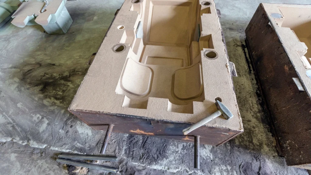
Understanding the various types of patterns is crucial for successful sand casting. Each type serves specific purposes and production needs:
- Flat Back Patterns: These patterns are pressed into the drag (bottom part) of the sand mold, with an unmolded cope (top half) clamped on top. They're ideal for simpler designs with one flat surface.
- Split Patterns: Designed in multiple parts, these patterns allow for more complex geometries. Each section can be impressed into different parts of the mold and removed without damaging the cavity.
- Match Plate Patterns: These patterns are mounted on plates, enabling simultaneous pressing of both mold halves. They're particularly efficient for high-volume production environments.
- Sweep Patterns: Using a rotating blade with a shaped profile, these patterns carve the sand around an axis, similar to a lathe creating negative space. They're perfect for symmetrical, circular castings.
- Gated vs. Loose Patterns: While loose patterns replicate just the final object, gated patterns include the metal feeding system within the pattern itself, reducing the need for hand-cut channels.
Segmented Patterns: For large or complex castings, segmented patterns are constructed in sections for easier handling and assembly. This approach simplifies transport, reduces weight, and enhances pattern durability, making it ideal for producing oversized components.
- Core Prints: These are projections on the pattern that create recesses in the mold to position and support cores accurately, ensuring proper formation of internal cavities in the casting.
Materials Used for Patterns and Their Selection Criteria
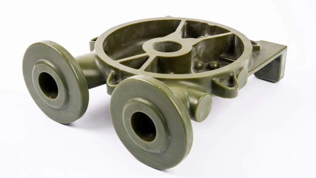
Patterns can be made from various materials, each chosen based on specific requirements of the casting process, the complexity of the design, and the number of casts to be produced. Common materials include:
- Wood: Traditional and widely used due to its ease of machining and cost-effectiveness. Best suited for prototypes and small production runs.
- Metal: Preferred for high-volume production due to its durability. Metals like aluminum and cast iron are common choices.
- Plastic: Offers excellent surface finish and dimensional stability. Used in both prototype and production patterns.
- Foam: Utilized in lost foam casting processes, foam patterns are vaporized upon contact with molten metal, allowing for intricate designs.
The selection criteria often hinge on factors such as the expected lifespan of the pattern, detail complexity, and the casting’s dimensional accuracy requirements.
Design Considerations for Patterns
Designing a pattern requires foresight and planning to address challenges that may arise during the casting process. Key considerations include:
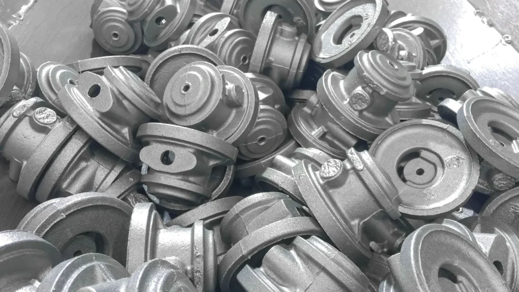
Draft Angles: Slight tapers applied to vertical surfaces of the pattern to facilitate its removal from the mold without damaging the mold cavity.
Cores and Core Prints: Cores create hollow sections or internal cavities in the cast. Core prints are extensions on the pattern that form recesses in the mold, which support the cores during the casting process.
Shrinkage Allowance: An adjustment made to the pattern dimensions to compensate for the shrinkage of metal as it cools and solidifies. Different metals have different shrinkage rates, requiring precise calculations to ensure the final cast matches the desired dimensions.
- Cast iron: 1/10 to 5/32 inch per foot
- Steel: 1/8 to 1.4 inch per foot
- Aluminum: 1/16 to 5/32 inch per foot
Machine Finish Allowance
The machine finish allowance (or machining allowance) is a critical consideration when a casting is expected to undergo post-casting machining operations, such as grinding, milling, or turning. Essentially, this allowance adds extra material to the final casting, ensuring that enough material remains for the machining process to refine the surface and achieve precise dimensional accuracy. Without this allowance, the cast part could end up too small after machining, potentially rendering it unusable.
One key aspect of machine finish allowance is its role in determining the placement of risers. Risers serve as reservoirs to compensate for metal shrinkage during cooling, but knowing that post-casting machining is required can help the pattern designer position them strategically. The metal around the riser area can be clamped or held securely during machining, ensuring a smooth and efficient post-casting process. This consideration is especially important in high-precision industries, where accuracy is paramount.
Distortion Allowance
The distortion allowance is a crucial step in pattern design, especially when working with metals that are known to distort during the cooling process. As the metal cools and solidifies, internal stresses can cause displacement, resulting in unwanted shape changes. To combat this, the pattern must be designed to account for such distortions, often through a process known as camber.
Camber involves intentionally modifying the pattern to counteract the predictable distortion that will occur when the metal solidifies. This modification allows the final casting to maintain the correct shape and dimensions. For example, if the metal is likely to contract or warp in a specific direction as it cools, the pattern is adjusted with the opposite distortion built in. This thoughtful modification helps the final product retain its intended form, ensuring consistency and precision.
Draft Allowance
In addition to machine finish and distortion allowances, draft allowance plays a vital role, particularly in sand casting patterns. Unlike investment casting, where precision molds are formed from a solid pattern, sand casting patterns must be able to be removed from the mold without damaging the fragile sand cavity. To make this removal process easier, the walls of the pattern are slightly tapered. This tapering, known as "draft," helps reduce the friction between the mold and the pattern, preventing damage and ensuring the integrity of the final casting.
Without a proper draft angle, the pattern could get stuck in the sand mold, causing deformation or cracking. This is why draft allowance is essential for sand casting patterns but unnecessary for investment casting, where the pattern is typically destroyed to retrieve the casting.
Critical Pattern Support Infrastructure
Every successful casting relies on a carefully designed system of channels and reservoirs:
- Pouring Cup: A tapered entry point that controls metal flow and captures slag during pouring.
- Sprue System: The main vertical channel directing metal from the pouring cup into the mold cavity.
- Runners: Horizontal channels distributing metal throughout different areas of the mold.
- Gates: Entry points where metal flows into the casting cavity, sized according to metal cooling rates.
- Risers: Reservoirs of liquid metal that prevent shrinkage defects by continuously feeding the cooling casting. These can be either blind (buried within the mold) or open (visible during pouring).
Pattern Finishing and Color Coding
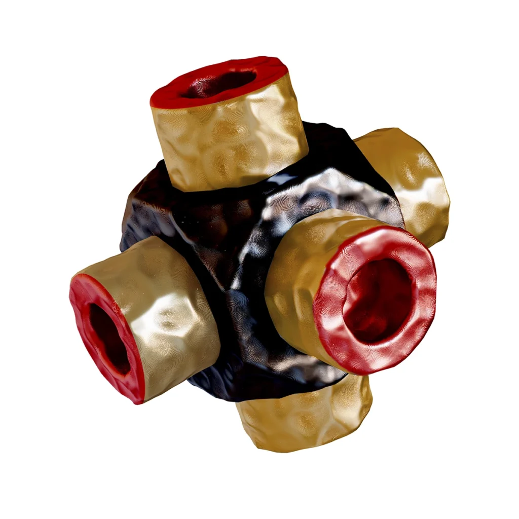
Professional pattern finishing involves a precise painting system:
- Three-Layer Application: Permanent patterns receive three carefully applied paint coats, ensuring durability and smooth surface finish.
- Color Coding Standards:
- Red surfaces indicate no machining needed
- Yellow marks areas requiring machining
- Black designates core surfaces
- Clear or unpainted areas show parting lines
- Paint Quality: Must be absolutely drip and crack-free to prevent mold defects.
Pattern Storage and Lifecycle Management
- Storage Requirements: Patterns need climate-controlled environments with good airflow to prevent warping and deterioration.
- Economic Considerations: Balancing storage costs against reproduction costs, especially with modern digital design capabilities.
- Digital Integration: CAD systems and digital storage now complement physical pattern storage, offering backup security and easy modification options.
Professional Expertise and Modern Integration
Today's pattern makers blend traditional craftsmanship with modern technology:
- Professional Background: Often coming from cabinetmaking or joinery backgrounds, pattern makers combine woodworking skills with metallurgical knowledge.
- Technical Integration: Modern pattern shops utilize CAD programs and predictive algorithms while maintaining hands-on expertise.
- Production Volume Considerations: Pattern makers must balance material selection, storage solutions, and durability requirements based on production volumes and client needs.
Step-by-Step Guide to Creating a Pattern
Creating a pattern is both an art and a science. Here’s a simplified overview of the steps involved:
- Design Conceptualization: Begin with a detailed drawing or a CAD model of the final casting, considering all necessary allowances and features.
- Material Selection: Choose the appropriate material for the pattern based on the casting requirements and production volume.
- Machining and Assembly: Carve, sculpt, or machine the pattern material to form the exact replica of the casting. For complex shapes, the pattern may be created in parts and then assembled.
- Finishing Touches: Apply surface finishes to the pattern to ensure it imparts a smooth surface to the mold. Add draft angles and finalize core prints.
- Testing and Adjustment: The pattern is often tested to ensure it produces a satisfactory mold. Adjustments may be made to refine the pattern before it’s used for full-scale production.
This phase, teeming with considerations and meticulous planning, underscores the pattern’s role as the cornerstone of the sand casting process. A well-conceived pattern is a harbinger of success, paving the way for a casting that meets the trifecta of fidelity to design, structural integrity, and aesthetic appeal.

