Posts by Align Manufacturing
Balloon Drawing Creation and GD&T for First Article Inspection
Introduction: The Visual Foundation of Quality Verification
In precision manufacturing, clear communication between engineering and quality teams is essential. Tolerances, dimensions, materials and geometric controls must be interpreted consistently to ensure every part meets its intended function.
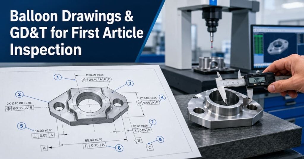
Balloon drawings, combined with Geometric Dimensioning and Tolerancing, or GD&T, provide a structured visual framework for First Article Inspection. They turn complex engineering drawings into traceable inspection records, helping manufacturers verify every required characteristic before full production begins.
For aerospace, automotive and other quality-sensitive applications, this process supports more reliable documentation, clearer accountability and fewer inspection gaps. It also complements broader quality planning processes such as PPAP levels for CNC machining and fabrication suppliers.
What Is a Balloon Drawing?
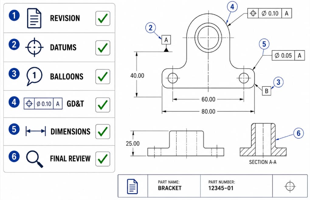
A balloon drawing is a controlled engineering drawing marked with sequentially numbered circles or “balloons”. Each balloon points to a specific characteristic that requires inspection, such as a dimension, tolerance, GD&T callout, material specification, surface finish or drawing note.
The balloon number links directly to the corresponding inspection result, often recorded in AS9102 Form 3 for First Article Inspection. This creates a clear trail from the engineering requirement to the measured result.
Balloon drawings help manufacturers:
- Ensure all inspectable characteristics are reviewed.
- Reduce ambiguity about what must be measured.
- Create traceable links between drawings and inspection records.
- Standardise inspection processes across teams.
- Support audits, customer approvals and quality documentation.
What Makes a Balloon Drawing Effective?
An effective balloon drawing should be clear, readable and easy for inspectors to follow.
| Element | Convention | Purpose |
| Balloon shape | Circular or oval | Makes each characteristic easy to identify |
| Balloon number | Sequential number starting at 1 | Gives each requirement a unique reference |
| Leader lines | Clear, direct lines | Prevents confusion about the intended feature |
| Placement | Outside the part outline where possible | Keeps dimensions and notes visible |
| Grouping | Separate balloons for separate requirements | Supports individual inspection accountability |
Each balloon should point to one measurable requirement. When a feature includes multiple requirements, such as a threaded hole with a depth, diameter and positional tolerance, each applicable requirement should be addressed clearly in the inspection record.
How Do You Create a Balloon Drawing?
Step 1: Verify the Drawing Revision
Before ballooning begins, confirm that the engineering drawing is the correct revision. The revision should match the purchase order, customer requirements and applicable First Article Inspection documentation.
Check that:
- The drawing revision is current.
- All dimensions, notes and GD&T callouts are legible.
- The file format is suitable for manual or digital ballooning.
- Customer-specific inspection requirements have been reviewed.
Using the wrong revision can cause significant quality and compliance issues, particularly when a design change affects form, fit or function.
Step 2: Number Characteristics Systematically
Balloon numbers should follow a logical inspection sequence. Many teams number features in the order an inspector will measure them across the part.
| Balloon range | Feature category | Purpose |
| 1–20 | Overall dimensions and datums | Establishes the inspection reference framework |
| 21–50 | Linear dimensions | Covers lengths, widths, heights and depths |
| 51–70 | Diameters and radii | Groups circular and cylindrical features |
| 71–90 | GD&T callouts | Identifies geometric controls |
| 91–99 | Surface finishes and notes | Captures secondary drawing requirements |
A logical sequence makes the inspection process more efficient and reduces the risk of missed characteristics.
Step 3: Address Complex Drawing Scenarios
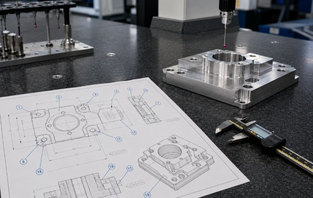
Multi-View Drawings
For drawings with front, top, side and section views, each characteristic should receive one balloon number, even if the feature appears in more than one view. This avoids duplicate measurement records.
Assembly Drawings
Assembly drawings may require separate balloon sequences for components and assembly-level requirements. These can include torque values, interface dimensions, fastener specifications and fit requirements.
Model-Based Definition
In model-based definition environments, inspection characteristics may be attached directly to 3D CAD geometry rather than a conventional 2D drawing. These semantic annotations still need to provide clear traceability between the design requirement, inspection method and measurement result.
What Is GD&T?
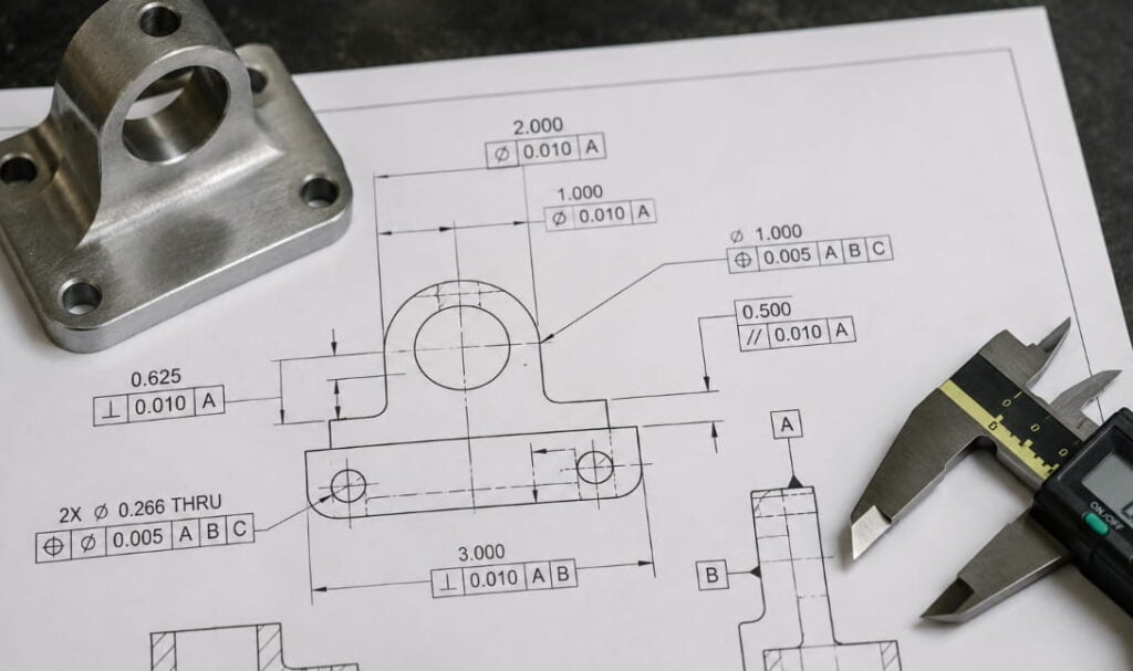
Geometric Dimensioning and Tolerancing (GD&T) is a standardised engineering language used to define how a component’s features must be manufactured and inspected. Rather than specifying only basic sizes, GD&T uses recognised symbols, tolerance values and datum references to control requirements such as position, flatness, perpendicularity, parallelism and runout. This gives manufacturers and quality teams a clearer understanding of design intent, helping ensure parts fit, function and assemble correctly while allowing controlled production variation.
For parts produced through processes such as precision CNC machining, GD&T helps ensure that critical features are inspected according to functional requirements rather than only basic dimensional limits.
How Is GD&T Used in First Article Inspection?
GD&T is particularly important during First Article Inspection because it defines how geometric characteristics must be verified. A standard dimension may state the size of a feature, but GD&T explains how that feature must relate to surrounding surfaces, axes or datum references.
GD&T can define:
- The geometric requirement being controlled.
- The allowable variation.
- The datum reference frame required for measurement.
- The material condition modifier affecting inspection setup.
- The relationship between multiple features.
Understanding these controls is essential because one Feature Control Frame may create several separate inspection requirements.
How Should Feature Control Frames Be Ballooned?
A Feature Control Frame, or FCF, is the rectangular GD&T box that defines a geometric requirement. It may include a geometric symbol, tolerance value, material condition modifier and datum references.
| FCF component | Inspection implication | Ballooning approach |
| Geometric characteristic symbol | Defines what must be measured | Balloon the geometric requirement clearly |
| Tolerance value | Defines allowed variation | Record the complete tolerance |
| Material condition modifier | May affect gaging and setup | Include the modifier in the inspection record |
| Datum references | Establish measurement orientation | Verify relevant datum features separately |
Each distinct requirement should be traceable. For example, a positional tolerance for a hole may require inspection of the hole diameter, the location of the hole relative to datums and the condition of the datum features themselves.
What GD&T Characteristics Commonly Appear in FAI?
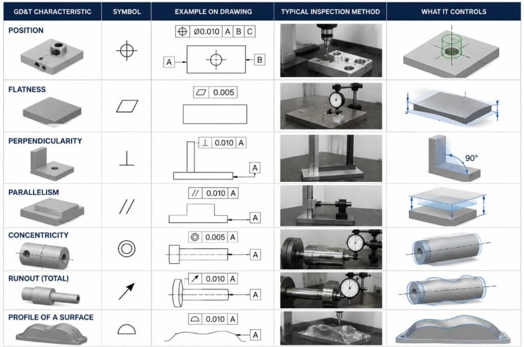
| GD&T characteristic | Typical inspection method | FAI consideration |
| Position | CMM or functional gage | Review datum references and material condition |
| Flatness | Surface plate and indicator | Measured without a datum reference |
| Perpendicularity | CMM, square or indicator | Establish the datum first |
| Concentricity | CMM or specialised measurement method | Often confused with runout |
| Profile of a surface | CMM or contour gage | May control complex surface form |
| Runout | Rotational fixture and indicator | Controls form and location together |
| Parallelism | Surface plate and height gage | Requires a datum reference |
| Circular runout | Rotational inspection | Controls individual circular sections |
| Total runout | Rotational inspection with axial measurement | Controls variation across the complete surface |
The appropriate method depends on the required tolerance, part geometry, available equipment and customer requirements.
How Can Digital Ballooning Software Improve FAI?
Digital ballooning software can make the FAI process more efficient by helping teams identify dimensions, apply balloon numbers and generate inspection documentation.
Common digital ballooning features include:
- PDF, TIFF and CAD drawing import.
- Automated dimension and GD&T recognition.
- Balloon numbering and placement tools.
- Revision comparison.
- AS9102 Form 3 export support.
- CMM data integration.
- Collaborative drawing review.
Digital tools are especially useful when managing complex drawings, recurring part families or design revisions. However, software should support engineering judgement rather than replace it. Review is still necessary to ensure every characteristic is correctly identified and linked.
How Do Balloon Drawings Connect to AS9102 Form 3?
Every balloon number on the drawing should correspond directly to a characteristic entry in AS9102 Form 3. This allows an auditor, customer or quality engineer to trace a measured value back to the exact drawing requirement.
| Balloon drawing element | Form 3 requirement | Key consideration |
| Balloon number | Characteristic number | Must match exactly |
| Dimension or callout | Requirement | Record the full specification and tolerance |
| Actual measurement | Inspection result | Record the actual value, not only pass or fail |
| Inspection equipment | Measurement method | Use clear, specific equipment references |
| Acceptance status | Conformance result | Support results with objective evidence |
For more context on whether a complete or limited FAI is required after a change, see our guide to partial vs full First Article Inspection for aerospace suppliers.
How Should Complex Characteristics Be Documented?
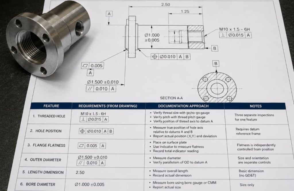
Some balloons represent requirements that need multiple measurements. A threaded hole with positional control, for example, may include:
- Thread size and pitch.
- Thread depth.
- Hole depth.
- Countersink specification.
- Positional tolerance relative to datums.
In these cases, the FAI documentation may require several Form 3 entries connected to one balloon number, or a detailed requirement description that captures every applicable condition.
The main goal is to ensure nothing is missed and every recorded measurement can be traced back to the drawing.
How Are SPC Characteristics Handled in Balloon Drawings?
Some critical characteristics may require Statistical Process Control, or SPC, in addition to First Article Inspection. These features may be marked with special symbols or notes to indicate sampling, criticality or control-plan requirements.
| Balloon notation | Meaning | Documentation approach |
| 15* | SPC characteristic | Reference the relevant control plan |
| 15 (n=5) | Sample size of five | Include sampling requirements |
| 15 Ⓢ | Safety-critical characteristic | Highlight acceptance criteria |
| 15 Ⓒ | Critical characteristic | Apply additional control measures |
SPC requirements should be reviewed early because they may affect inspection frequency, data collection methods and production control plans.
How Should Family-of-Parts Drawings Be Ballooned?
When one drawing applies to multiple related part numbers, the ballooning process should remain consistent while clearly identifying which characteristics apply to each variation.
- Create a matrix showing which requirements apply to each part number.
- Balloon all relevant characteristics.
- Mark non-applicable characteristics as “N/A” where required.
- Maintain traceability between the part number, drawing revision and FAI record.
This approach is particularly useful for similar machined, cast or fabricated components where the main geometry remains consistent but selected features vary.
How Should Supplier-Provided Characteristics Be Managed?
When suppliers provide sub-components with their own FAI documentation, their ballooned drawings and inspection records should be retained as supporting evidence.
Manufacturers should:
- Reference supplier balloon numbers where appropriate.
- Include supplier FAI documentation in the complete inspection package.
- Maintain lot, batch or serial number traceability.
- Verify supplier documentation during incoming inspection.
- Confirm that supplier documents match the correct drawing revision.
Strong document control is essential when managing multiple suppliers or manufacturing locations. Our guide to manufacturing documentation control and material traceability provides further guidance on managing inspection records, revisions and supplier documentation.
How Do You Check a Balloon Drawing Before Submission?
Before submitting a ballooned drawing with an FAI package, verify that:
- The drawing revision matches the purchase order and customer requirements.
- Every required dimension, tolerance, note and GD&T callout is ballooned.
- Reference dimensions are excluded unless specifically required.
- Balloon numbers are sequential and unique.
- Leader lines clearly identify the correct characteristic.
- GD&T callouts and datum features are fully addressed.
- No balloons overlap or obscure important drawing information.
- Title block information remains visible.
- The drawing is stored within the required document-control system.
What Are the Most Common Balloon Drawing Errors?
| Error type | Example | Prevention |
| Missing characteristics | Surface-finish requirement not ballooned | Use a systematic scan pattern |
| Duplicate numbering | Two balloons labelled “15” | Use validation tools or a manual checklist |
| Ambiguous leaders | Leader line crosses several dimensions | Use direct and clear placement |
| Wrong revision | Ballooning Rev B instead of Rev C | Verify revision before starting |
| Reference dimensions included | Ballooning values in parentheses | Understand drawing conventions first |
Conclusion: Why Do Balloon Drawings Matter in FAI?
Balloon drawings and GD&T provide the visual language that turns engineering requirements into measurable quality actions. During First Article Inspection, they help ensure that every relevant feature is identified, measured, documented and traceable.
As manufacturing increasingly uses digital models, CMM data and automated reporting tools, the principles remain the same: clear requirements, accurate measurement and dependable traceability. Whether a part is made through machining, fabrication or casting, a well-prepared balloon drawing helps connect design intent with manufacturing reality.
At Align Manufacturing, we support customers with quality-focused sourcing, engineering and production management across Southeast Asia. From precision machined components to gravity casting Vietnam programmes, we help ensure drawings, inspection requirements and manufacturing processes remain aligned from initial sample approval through repeat production. For teams evaluating sourcing options, our guide to why Vietnam is a hidden gem for gravity casting explains how production capability and quality planning can work together.
FAQ: Balloon Drawings and GD&T for FAI
What is the difference between a ballooned drawing and an inspection drawing?
A ballooned drawing is specifically used to identify and trace FAI characteristics, often linking each balloon number to AS9102 Form 3. An inspection drawing is a broader term for any drawing used during inspection. All ballooned drawings are inspection drawings, but not all inspection drawings are ballooned for FAI.
Should reference dimensions be ballooned?
Usually, no. Reference dimensions, commonly shown in parentheses, are for information only and do not normally require verification. Ballooning them can create unnecessary inspection work unless the customer specifically requests it.
How should repeated identical features be ballooned?
For repeated features, such as eight identical holes, manufacturers may balloon the requirement once and note “8X”, or assign separate balloon numbers to each feature. Customer requirements and the inspection plan should determine the preferred approach.
What software can create balloon drawings from CAD models?
Several tools support digital ballooning, including InspectionXpert, 1Factory, Discus, Balloonist and BalloonX. The best option depends on CAD compatibility, reporting needs and whether integrations with CMM, ERP or quality systems are required.
How should composite position tolerances be ballooned?
Composite position tolerances require careful interpretation because the upper and lower segments control different geometric relationships. Each segment should be evaluated independently, and separate inspection records may be required where the requirements differ.
What balloon numbering convention works best for assemblies?
Common approaches include sequential numbering across the full assembly or separate number ranges for each component. The key requirement is consistency and clear traceability to the bill of materials and inspection record.
How do model-based definition systems affect ballooning?
In model-based definition systems, semantic annotations can be connected directly to CAD geometry rather than placed as graphical balloons on a 2D drawing. These annotations can still provide the characteristic identification and traceability needed for inspection.
Can a supplier’s balloon drawing be modified for internal FAI use?
Supplier documentation should normally be retained as supporting evidence. Manufacturers should create their own ballooned drawing from the applicable manufacturing drawing to maintain document control and traceability.
How should metric and imperial units be handled?
Use the primary units specified on the drawing and record measured values consistently. Where conversions are necessary, document them clearly in the inspection records to avoid confusion.
How do engineering change orders affect ballooned drawings?
When an engineering change order updates a drawing, the ballooned drawing must be revised to match the latest revision. For delta FAIs, only changed characteristics may need reinspection, but the documentation must clearly identify the updated drawing and affected features.
High-Volume Brass Parts: When to Choose Stamping Over CNC Machining

What Is the Best Process for High-Volume Brass Parts?
In brass component manufacturing, the choice between metal stamping and CNC machining can shape the cost, speed, and consistency of a production project. For high-volume applications, metal stamping is often the stronger option for cost efficiency, production speed, and material utilisation, while CNC machining is better suited for precision, flexibility, and complex geometries.
This guide explains the technical, economic, and practical factors that should guide process selection for brass parts produced in quantities above 5,000 units.
Why Is Brass Used for Stamping and CNC Machining?
Brass is an alloy of copper and zinc with properties that make it suitable for both stamping and machining. Its ductility, corrosion resistance, and attractive finish make it common in plumbing, automotive, electronics, architectural hardware, and industrial components.
The workability of brass depends heavily on zinc content. Alpha brass, with less than 35% zinc, offers strong formability for stamping. Alpha-beta brass provides higher strength for more demanding applications.
Key Brass Properties That Affect Manufacturing
- Ductility: Brass can be formed into complex stamped shapes without cracking when the correct alloy and thickness are selected.
- Machinability: Free-machining brass alloys such as C360 provide strong chip formation and tool life.
- Thermal Conductivity: Heat transfer affects die design, tool wear, and machining parameters.
- Corrosion Resistance: Natural resistance to tarnish and corrosion can reduce post-processing needs.
Why Is Metal Stamping Often Better for High-Volume Brass Parts?
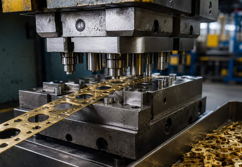
Metal stamping transforms flat brass sheets or coils into finished components through controlled deformation. Custom dies and punches are mounted in hydraulic, mechanical, or servo presses to cut, bend, draw, or form the material.
Stamping Turns Sheet Brass into Repeatable Parts
Common stamping operations include:
- Blanking: Cutting the basic outline from sheet metal.
- Piercing: Creating holes and cutouts.
- Bending: Forming angled features.
- Drawing: Stretching material into deeper shapes.
- Coining: Creating precise surface details through compression.
Progressive dies can perform several operations in sequence, making stamping highly efficient once tooling is complete.
Stamping Reduces Unit Cost at Scale
Once tooling is established, the cost per part drops significantly. For large production runs, stamping is usually more economical than CNC machining because it reduces cycle time, labour input, and material waste.
Stamping Supports Faster Production
Stamping operations can produce parts in seconds or fractions of a second. A single stamping line can often match the output of several CNC machines for simple or moderately complex parts.
Stamping Improves Material Utilisation
Because stamping forms parts from sheet or coil stock, it typically creates less waste than subtractive machining. Nesting optimisation can further improve material use by arranging parts efficiently on the strip.
Stamping Delivers Consistency Across Large Runs
Modern stamping presses can maintain repeatable dimensions across long production runs. For many functional brass components, stamped tolerances are accurate enough without needing every feature to be CNC-machined.
Stamping Has Clear Design Limits
Stamping works best for parts that can be formed from flat patterns. Internal features, complex three-dimensional contours, deep pockets, and very tight tolerance requirements may be difficult or uneconomical to stamp.
Other limitations include:
- High upfront tooling cost.
- Tooling development lead time.
- Springback after forming.
- Less flexibility if the design changes after tooling is made.
When Is CNC Machining Better for Brass Components?
CNC machining removes material from solid brass stock using computer-controlled cutting tools. It is a subtractive process that offers strong precision and design flexibility.
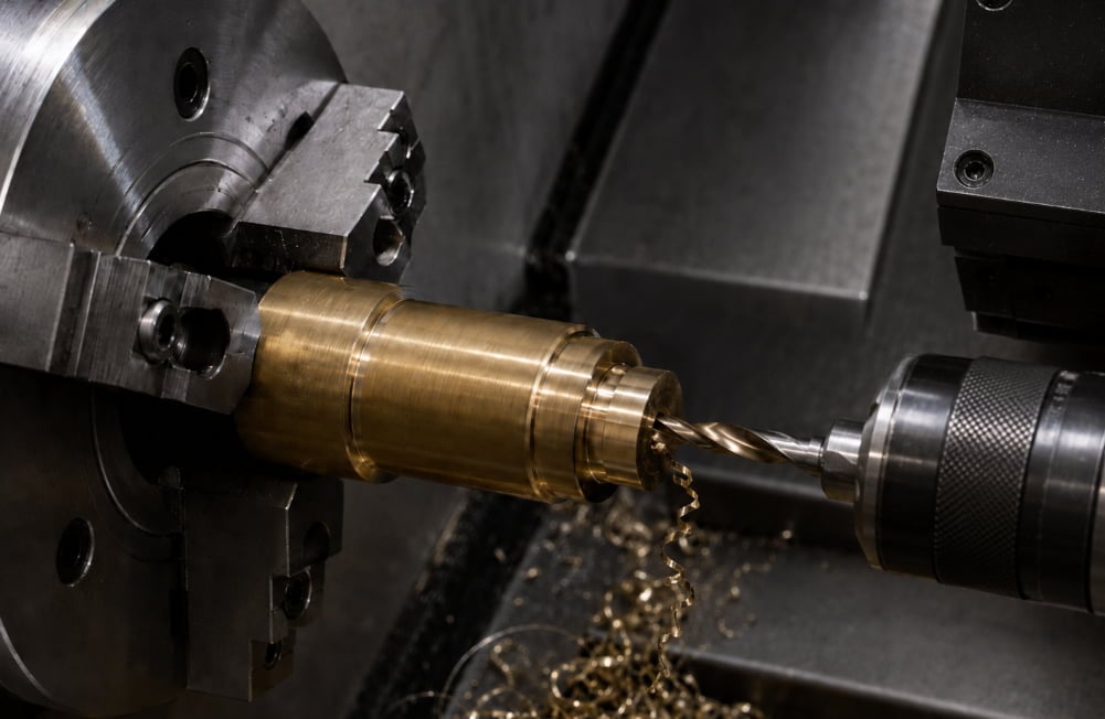
CNC Machining Delivers Tight Tolerances
CNC machining is ideal when brass parts require tight dimensional control, precision threads, complex internal profiles, or fine surface finishes. It is often the better choice for small batches, prototypes, and parts with geometries that cannot be stamped.
CNC Allows More Design Flexibility
Multi-axis CNC machines can create complex contours, internal features, precise angular relationships, and detailed surfaces that are difficult or impossible to achieve through stamping alone.
CNC Is Faster for Prototypes and Design Changes
Because CNC machining does not require dedicated dies, parts can often be produced soon after the design is finalised. This makes it useful for engineering validation, early production, and parts that may still change.
CNC Becomes Expensive at High Volume
For large-volume brass production, CNC machining has higher per-unit costs because it requires more machine time and creates more material waste. Skilled programming, machine setup, tooling wear, and labour also add to the total cost.
How Do Stamping and CNC Machining Compare for Brass Parts?
| Factor | Metal Stamping | CNC Machining | Better for High Volume |
| Cost per unit | Very low after tooling is amortised | Higher due to machine time and waste | Stamping |
| Production speed | Very fast | Slower per part | Stamping |
| Initial investment | High tooling cost | Lower setup cost | CNC |
| Precision | Good for many functional parts | Higher precision capability | CNC |
| Design flexibility | Limited to formable shapes | Very flexible | CNC |
| Material utilisation | Strong with nesting optimisation | Lower due to material removal | Stamping |
| Setup time | Longer due to tooling | Shorter for simple setups | CNC |
| Design changes | Expensive after tooling | Easier to update | CNC |
| Surface finish | Good, may need secondary finishing | Strong directly from machining | CNC |
| Best volume range | Medium to high volume | Prototype to low volume | Stamping for scale |
What Volume Makes Brass Stamping Cost-Effective?
The break-even point between stamping and CNC machining depends on part complexity, material cost, tolerance requirements, tooling cost, and expected lifecycle volume. For simple brass brackets, clips, terminals, and housings, stamping can become attractive at relatively modest production volumes. For more complex formed parts, higher volumes may be needed to justify the tooling investment.
A Practical Volume Decision Framework
- Under 500 units: CNC machining usually makes more sense.
- 500 to 5,000 units: A detailed cost comparison is needed.
- 5,000 to 50,000 units: Stamping often becomes more competitive.
- Above 50,000 units: Stamping is usually the stronger economic option for suitable designs.
Cost Comparison Example
Consider a brass electrical connector housing measuring 2″ × 1″ × 0.5″:
- CNC machining: Higher unit cost, lower upfront investment.
- Stamping: Higher tooling cost, lower unit cost after production begins.
- Break-even: Depends on tooling complexity, material thickness, tolerance requirements, and annual volume.
- At higher quantities: Stamping usually reduces the total cost significantly if the part is designed for forming.
What Should Engineers Consider When Stamping Brass?
Not all brass alloys behave the same during stamping. Alloy selection, material thickness, grain direction, lubrication, and die design all affect the final result.
Choose the Right Brass Alloy for Stamping
- C260 Cartridge Brass: Strong ductility and corrosion resistance. Often suitable for deep drawing and formed parts.
- C360 Free-Cutting Brass: Excellent machinability but lower formability. Better suited to CNC machining or secondary machined features.
- C464 Naval Brass: Improved corrosion resistance due to tin content. Common in marine-related applications.
- C485 Leaded Brass: Good machinability, though lead content may be restricted depending on regulations and end-use requirements.
Design Dies Around Brass Behaviour
Springback Compensation: Brass partially returns toward its original shape after forming, so dies may need over-bending to achieve final dimensions.
Grain Direction: Rolled brass sheet has directional properties. Material orientation can affect bend quality and cracking risk.
Lubrication: Proper lubrication helps prevent galling, material pickup, and die wear during forming.
Tooling Materials: Tool steel, carbide, and specialised coatings can improve die life for high-volume stamping.
Where Are Stamped Brass Parts Commonly Used?
Stamped brass parts are used across industries where electrical conductivity, corrosion resistance, appearance, and repeatability matter.
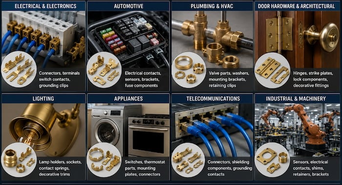
Automotive Components
Automotive suppliers often use stamped brass for terminals, connectors, clips, contacts, and small housings. Stamping is especially useful when designs are stable and annual volumes are high.
Electronics Connectors
Brass is widely used in connector shells, terminals, contacts, and shielding components. Progressive stamping is well suited to these parts because they often require consistent geometry, thin material, and high output.
Architectural Hardware
Brass door hardware, lock components, plates, trims, and decorative pieces may use stamping when the design can be formed from sheet stock. Secondary finishing can then create the desired appearance.
Can Stamping and CNC Machining Be Combined?
Yes. Many brass components benefit from a hybrid process where stamping creates the main shape and CNC machining adds precision features.
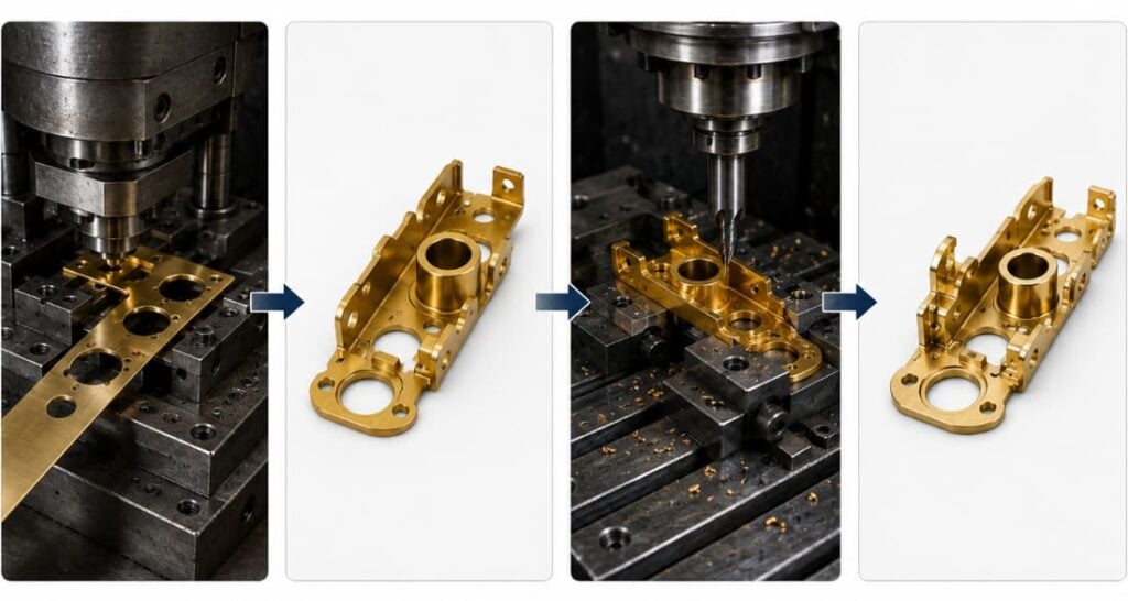
Hybrid Manufacturing Balances Cost and Precision
A common hybrid process includes:
- Primary forming: Stamping creates the basic shape, bend features, flanges, and cutouts.
- Secondary machining: CNC adds precision holes, threads, sealing surfaces, or complex internal features.
- Finishing: Plating, polishing, coating, or deburring is added when required.
This approach combines the speed and cost advantages of stamping with the accuracy of CNC machining.
Example: Brass Valve Body Production
A brass valve body may be formed or cast into its basic shape first, then CNC-machined for threads, sealing faces, and internal passages. For readers comparing brass processes beyond stamping and CNC, our guide to brass valve manufacturing provides useful context on casting and forging choices for pressure-related parts.
What Trends Are Changing Brass Component Manufacturing?
Manufacturing technology continues to improve both stamping and CNC machining. The biggest changes involve automation, digital simulation, quality monitoring, and sustainability.
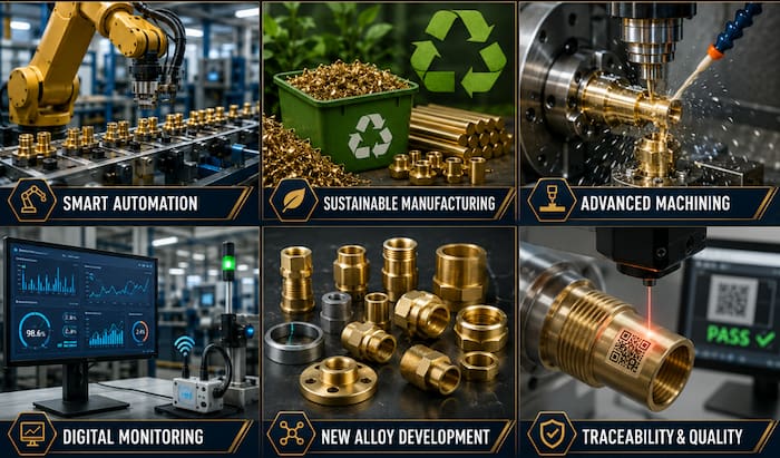
Smart Presses Improve Stamping Control
Modern stamping presses can monitor force, alignment, tool condition, and production variation in real time. This helps reduce defects and improve preventive maintenance.
Digital Simulation Reduces Tooling Risk
Digital forming simulations help engineers predict springback, thinning, cracking, and die performance before physical tooling is built. This can reduce trial-and-error during die development.
Sustainable Manufacturing Is Becoming More Important
Brass scrap from both stamping and CNC machining can be recycled. Stamping often produces less waste per part, while CNC machining generates chips that must be collected and processed efficiently.
Energy-efficient presses, improved tool coatings, and better lubricant management can also reduce environmental impact.
How Should You Choose Between Stamping and CNC Machining?
The best process depends on volume, geometry, tolerance, timeline, material, and long-term design stability.
Follow a Practical Selection Process
- Assess production volume: Estimate annual demand and product lifecycle.
- Review part geometry: Identify whether the design can be formed from sheet or coil stock.
- Model total cost: Include tooling, material, labour, scrap, maintenance, and secondary operations.
- Check timeline: CNC is faster for prototypes, while stamping requires tooling lead time.
- Match quality requirements: Use CNC for critical tight-tolerance features.
- Evaluate design stability: Avoid expensive stamping dies if the part is likely to change.
Ask These Questions Before Choosing
- Will the design stay stable throughout the product lifecycle?
- What is the realistic annual production volume?
- Which features truly require tight precision?
- Can the part be redesigned for stamping?
- Is the timeline long enough for tooling development?
- Would a hybrid stamping and CNC process reduce cost without sacrificing quality?
Conclusion
The choice between stamping and CNC machining for high-volume brass parts is a strategic manufacturing decision. CNC machining offers excellent precision, flexibility, and speed for prototypes or low-volume production. Metal stamping, however, delivers stronger economics when volumes increase and the part geometry is suitable for forming.
For manufacturers, the best path starts with honest volume forecasting, design-for-manufacturability review, and total cost modelling. In many cases, a hybrid approach offers the best balance by using stamping for the main shape and CNC machining for precision details.
At Align Manufacturing, we help customers assess the most suitable production route for metal parts across Vietnam, Thailand, and India. Whether the project involves CNC machining, fabrication, casting, or gravity casting Vietnam, our role is to connect engineering requirements with reliable manufacturing execution.
Frequently Asked Questions
What is the minimum volume that makes brass stamping cost-effective compared to CNC machining?
The break-even point depends on part complexity, tooling cost, material thickness, and tolerance requirements. Simple brass parts may justify stamping at lower volumes, while complex formed parts usually need higher volumes to offset tooling investment.
Can stamped brass parts achieve the same precision as CNC-machined parts?
Stamped brass parts can be highly repeatable, but CNC machining is generally better for very tight tolerances, precision threads, and complex internal features. For demanding parts, stamping can be combined with secondary CNC machining.
How do lead times compare between stamping and CNC machining?
CNC machining usually has a shorter initial lead time because it does not require dedicated dies. Stamping needs tooling development, but once tooling is approved, production speed is much faster.
What brass alloys are best suited for high-volume stamping?
C260 cartridge brass is commonly suitable for forming because of its ductility. C360 is better for machining, while C464 may be selected for improved corrosion resistance in marine applications.
How does material thickness affect the choice between stamping and CNC machining?
Thinner brass sheet is generally more suitable for stamping. Thicker brass stock may require more forming force or may be more practical to machine, depending on the shape and tolerance requirements.
What are the main quality control challenges with brass stamping?
Common challenges include die wear, springback variation, galling, lubrication control, and dimensional consistency during long runs. These are managed through die maintenance, process monitoring, inspection, and proper material control.
Can stamped brass parts be plated or finished after forming?
Yes. Stamped brass parts can be plated, polished, coated, or finished after forming. The design should account for edge condition, recess access, and finish coverage.
How does part complexity affect the economics of brass stamping?
More complex stamped parts require more complex tooling, which increases upfront cost. If the part needs many forming stations or tight precision features, CNC machining or a hybrid process may be more suitable.
What environmental considerations differ between stamping and CNC machining?
Stamping often creates less waste per part, while CNC machining generates recyclable brass chips. Both processes can be managed responsibly through scrap recycling, lubricant control, and energy-efficient equipment.
How has automation changed stamping and CNC machining?
Automation improves both processes. Stamping benefits from automated presses, feeding systems, inspection, and die change systems. CNC benefits from pallet systems, robotic loading, and automated inspection.
What design changes can make brass parts easier to stamp?
Useful design changes include adding generous bend radii, avoiding deep draws where possible, maintaining consistent wall thickness, reducing unnecessary hole sizes, and designing features that suit progressive die production.
How do maintenance costs compare between stamping and CNC machining?
Stamping maintenance is mainly tied to die sharpening, repair, and replacement. CNC maintenance involves cutting tools, calibration, spindle condition, and machine upkeep. The better option depends on volume, part complexity, and production schedule.
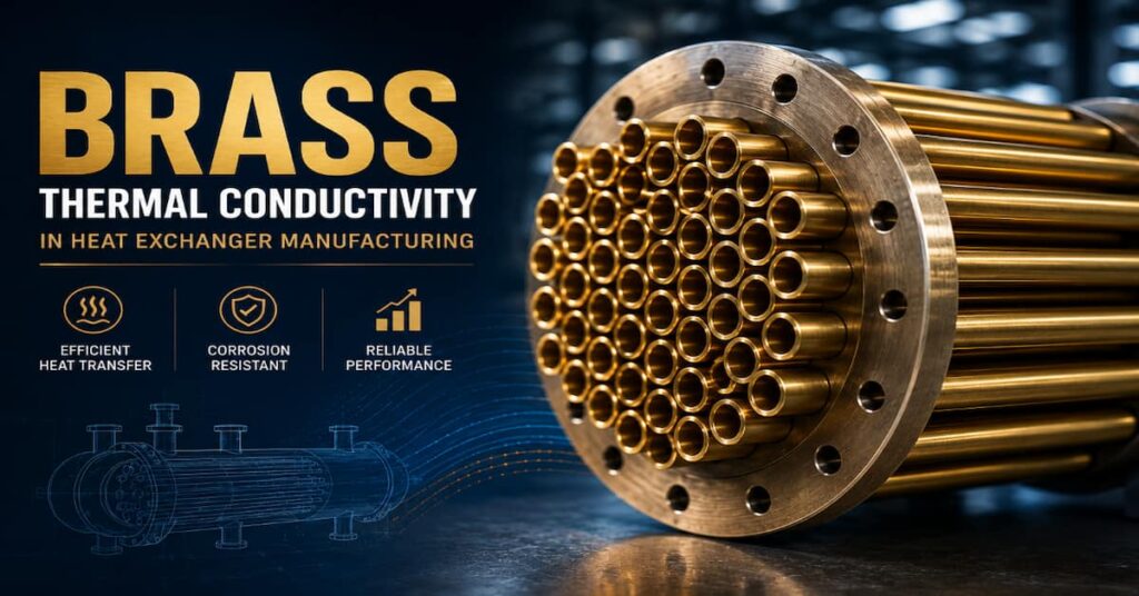
Utilizing Brass Thermal Conductivity in Heat Exchanger Manufacturing
Suggested URL: /brass-thermal-conductivity-heat-exchanger-manufacturing
Heat exchangers form the thermal backbone of HVAC systems, marine cooling, power generation, and industrial process equipment. Material selection for heat exchanger tubes and components directly impacts thermal efficiency, corrosion resistance, service life, and manufacturing economics. Brass alloys, particularly copper-zinc alloys, offer a strong balance of thermal performance, fabricability, and cost-effectiveness that has made them reliable materials in heat transfer applications for over a century.
Understanding how brass thermal conductivity changes with alloy composition, temperature, and manufacturing processes helps engineers optimise heat exchanger designs for specific operating environments. This guide examines brass thermal properties, alloy selection criteria, and manufacturing considerations for heat exchanger applications.
What Is Thermal Conductivity in Heat Exchanger Materials?
Thermal conductivity measures a material’s ability to conduct heat, quantified in watts per metre-kelvin (W/m·K). Higher values indicate more efficient heat transfer. Thermal conductivity depends on atomic structure, electron mobility, temperature, and material purity.
Metals Conduct Heat Through Electron Transport and Lattice Vibrations
Metals conduct heat through two primary mechanisms:
Electron transport: Free electrons in metallic bonds carry thermal energy efficiently. According to the ASM Handbook, pure copper’s high thermal conductivity, around 398 W/m·K at room temperature, is linked to its free electron structure.
Lattice vibrations, or phonons: Atomic vibrations move through the crystalline structure and contribute to thermal transport. This mechanism is more dominant in non-metallic materials, but it still contributes to heat transfer in metals.
Alloying elements disrupt regular crystalline structures and scatter electrons, generally reducing thermal conductivity compared to pure metals. However, alloying is often necessary to improve strength, corrosion resistance, machinability, or other performance requirements.
What Is the Thermal Conductivity Range of Brass?
Commercial brass alloys typically exhibit thermal conductivities of approximately 100–150 W/m·K. This is substantially lower than pure copper and lower than aluminium, which is commonly around 205 W/m·K, but far above stainless steel, which is often around 15–25 W/m·K. This positions brass as a practical compromise between heat transfer, corrosion resistance, and manufacturing performance.
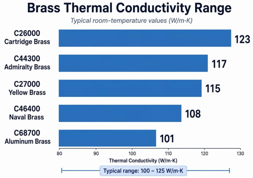
| Alloy | UNS | Thermal Conductivity (W/m·K) | Notes |
|---|---|---|---|
| Cartridge Brass | C26000 | 123 | Standard brass with good balance |
| Yellow Brass | C27000 | 115 | Similar to C26000 |
| Admiralty Brass | C44300 | 117 | Arsenic-inhibited for seawater |
| Naval Brass | C46400 | 108 | Higher strength, lower conductivity |
| Aluminum Brass | C68700 | 101 | Aluminum addition reduces conductivity |
Thermal conductivity generally decreases with increasing zinc content and additional alloying elements. Pure copper’s 398 W/m·K can drop to approximately 115–125 W/m·K in common brasses containing 30–40% zinc.
Brass Conductivity Can Increase at Higher Temperatures
Thermal conductivity varies with temperature. For brass alloys commonly used in heat exchangers:
At 20°C (68°F): 100–125 W/m·K
At 100°C (212°F): 115–140 W/m·K
At 200°C (392°F): 125–150 W/m·K
This positive temperature coefficient can benefit heat exchanger performance, as conductivity may increase where heat transfer is most intensive. However, designers still need to account for the full operating temperature range when calculating thermal performance.
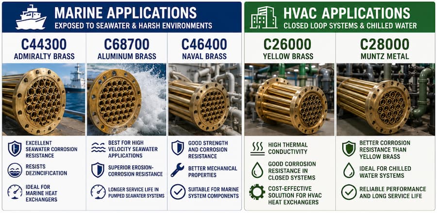
Which Brass Alloys Are Used in Heat Exchangers?
Different brass alloys serve different heat exchanger applications depending on thermal requirements, corrosion environment, and mechanical property needs.
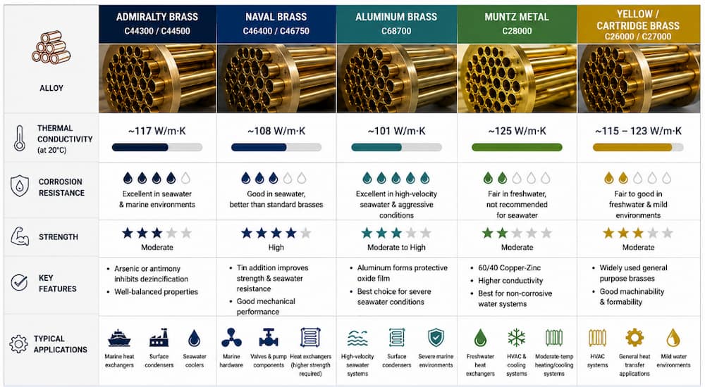
Admiralty Brass Balances Conductivity and Seawater Resistance
Admiralty brass, including C44300 and C44500, contains approximately 70–73% copper, 26–29% zinc, and small additions of tin and arsenic or antimony. The arsenic addition, typically 0.02–0.10%, helps inhibit dezincification corrosion in seawater and other aggressive environments.
Thermal properties:
- Thermal conductivity: around 117 W/m·K at 20°C
- Moderate thermal performance with excellent corrosion resistance
- Suitable for moderate-temperature applications
Applications:
- Surface condensers for power plants
- Distiller units in marine applications
- Heat exchangers handling seawater or brackish water
- Oil coolers and evaporators
Admiralty brass is a workhorse alloy for marine and coastal heat exchanger applications where seawater corrosion strongly influences material selection.
Naval Brass Offers Higher Strength for Loaded Components
Naval brass, including C46400 and C46750, contains approximately 59–62% copper, 0.5–1.0% tin, and the balance zinc. Tin improves strength and seawater corrosion resistance compared to standard brasses.
Thermal properties:
- Thermal conductivity: around 108 W/m·K at 20°C
- Lower conductivity due to higher tin content
- Improved mechanical strength
Applications:
- Propeller shafts and marine hardware
- Valve stems and pump components
- Heat exchanger components requiring higher strength
- Applications with moderate thermal requirements and mechanical loading
The strength advantage of naval brass may allow thinner wall designs, partially compensating for reduced thermal conductivity in certain applications.
Aluminum Brass Performs Well in Severe Seawater Conditions
Aluminum brass, including C68700, contains approximately 76–79% copper, 1.8–2.5% aluminum, and the balance zinc. Aluminum helps create a protective oxide film, improving corrosion resistance in high-velocity seawater.
Thermal properties:
- Thermal conductivity: around 101 W/m·K at 20°C
- Lower conductivity than admiralty brass
- Strong corrosion resistance for severe environments
Applications:
- High-velocity seawater heat exchangers
- Surface condensers with aggressive water conditions
- Applications where corrosion would limit the service life of other brasses
Although aluminum brass has lower thermal conductivity, it can provide better life-cycle performance in severe environments by reducing the risk of premature tube failure.
Muntz Metal Provides Higher Conductivity for Freshwater Systems
Muntz metal, or C28000, contains approximately 59–62% copper and the balance zinc. It is essentially a 60/40 brass without additional alloying elements.
Thermal properties:
- Thermal conductivity: around 125 W/m·K at 20°C
- Higher conductivity than admiralty or aluminum brass
- Lower corrosion resistance, making it more suitable for freshwater applications
Applications:
- Freshwater heat exchangers
- Moderate-temperature heating and cooling systems
- Applications where thermal performance outweighs corrosion concerns
What Design Factors Matter for Brass Heat Exchangers?
Effective heat exchanger design balances thermal performance, pressure drop, structural integrity, corrosion resistance, and manufacturing feasibility.
Tube Wall Thickness Controls Heat Transfer and Strength
Thinner walls improve thermal performance by reducing conductive resistance, but they must still withstand pressure, erosion, vibration, and corrosion. Typical heat exchanger tube wall thicknesses range from 0.5–2.0 mm, depending on diameter and service conditions.
Thermal resistance through the tube wall can be expressed as:
R_wall = ln(r_outer / r_inner) / (2 × π × k × L)
Where k is thermal conductivity and L is tube length. Higher conductivity reduces wall resistance, supporting improved heat transfer or reduced surface area requirements.
Tube Diameter Affects Surface Area and Pressure Drop
Smaller tube diameters provide higher surface area per unit volume and may increase heat transfer coefficients. However, they can also increase pressure drop and fouling susceptibility. Common brass heat exchanger tubes range from 6–50 mm in diameter.
Surface Enhancements Improve Heat Transfer
Internal or external surface enhancements, including grooves, fins, and turbulators, increase heat transfer area and promote turbulence. Manufacturing processes must accommodate these features while maintaining material integrity and dimensional consistency.
How Does Fouling Affect Brass Heat Exchanger Performance?
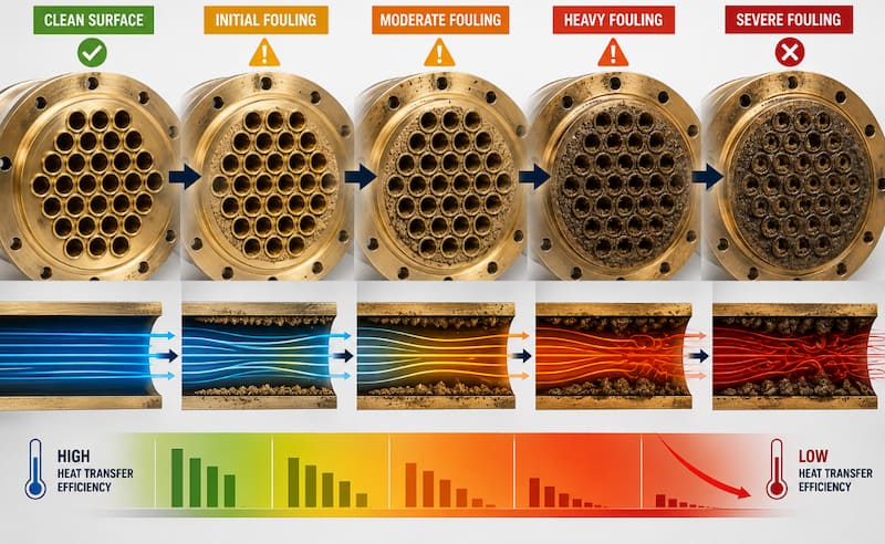
Fouling, or the deposition of materials on heat transfer surfaces, degrades performance over time. Brass’s smooth surface finish and corrosion resistance can reduce certain fouling mechanisms.
Particulate fouling: Smooth brass surfaces shed particles more readily than rougher materials.
Corrosion fouling: Proper brass alloy selection minimises corrosion product accumulation.
Biological fouling: Copper content provides natural biofouling resistance.
Biofouling resistance is especially valuable in marine and coastal applications, where biological growth can otherwise require frequent cleaning or chemical treatment.
Brass Helps Maintain Higher Overall Heat Transfer Coefficients
Heat exchanger thermal design uses overall heat transfer coefficients, or U-values, combining convective resistances and wall conduction:
1/U = 1/h_inner + R_wall + 1/h_outer + R_fouling
Where h represents convective heat transfer coefficients and R_fouling accounts for fouling layer resistance. Brass’s favourable thermal conductivity reduces R_wall, enabling higher U-values and more compact designs.
According to Begell House Publishers’ Heat Exchanger Design Handbook, brass tubes in typical water-to-water or water-to-air applications may achieve U-values of around 500–1,500 W/m²·K, depending on flow conditions and fouling state.
How Are Brass Heat Exchanger Components Manufactured?
Brass heat exchanger manufacturing includes tube production, component fabrication, assembly, and quality verification.
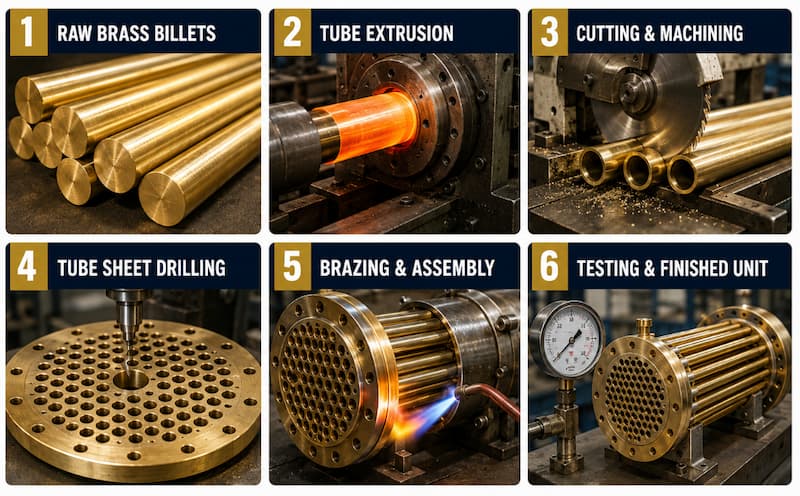
Seamless Tube Extrusion Supports High-Quality Tubing
High-quality heat exchanger tubes typically use seamless extrusion processes. Brass billets are heated to approximately 600–750°C and extruded through dies to form hollow tubes. Subsequent cold drawing achieves precise dimensional tolerances and surface finishes.
Manufacturing processes must preserve thermal conductivity through:
- Controlled annealing to relieve work hardening without excessive grain growth
- Minimising residual stresses that could affect thermal performance
- Maintaining alloy chemistry within specification limits
Heat exchanger tubes require tight dimensional tolerances, typically around ±0.05 mm on diameter, and defect-free surfaces. Eddy current and ultrasonic testing are commonly used to verify tube integrity.
Headers, Baffles, and Support Plates Require Accurate Fabrication
Heat exchanger headers, baffles, and support plates are typically fabricated from brass plate or castings.
Stamping and forming: Brass sheet can be stamped into header shapes, tube sheets, and baffles. Progressive dies help produce high volumes of components with consistent quality.
Machining: CNC machining produces complex features in headers and connections. Free-machining brass grades support drilling, tapping, and surface machining, while tool selection and chip control help manage brass’s thermal conductivity and tendency to gall.
Joining: Brazing is widely used for heat exchanger assembly because it creates metallurgical bonds with strong thermal and mechanical properties. Silver-based brazing alloys from the BAg series are often used for high-strength joints with good corrosion resistance.
How Can Corrosion Be Controlled in Brass Heat Exchangers?
Heat exchanger longevity depends on corrosion management during both manufacturing and service.
Surface Treatments Help Improve Corrosion Resistance
Common corrosion protection methods include:
Passivation: Chemical treatments that support protective oxide formation
Coatings: Organic or metallic coatings for severe environments
Cathodic protection: Sacrificial anodes for critical applications
Manufacturing cleanliness is also critical. Residual lubricants, fluxes, or contaminants can accelerate corrosion initiation, so thorough cleaning before shipment helps protect components during storage and early service.
Which Brass Alloys Work Best for Marine and HVAC Applications?
Heat exchanger service environments dictate alloy selection and design practice.
Marine Systems Need Strong Seawater Corrosion Resistance
Marine heat exchangers face severe corrosion challenges from seawater exposure.
Recommended alloys:
- Seawater cooling: Admiralty brass C44300 or aluminum brass C68700
- High-velocity seawater: Aluminum brass preferred for velocity above 2.5 m/s
- Seawater with sediment: Admiralty brass with enhanced wall thickness
Design considerations:
- Maintain water velocity between 1–3 m/s to reduce erosion-corrosion
- Avoid crevices where differential aeration corrosion can begin
- Design for inspection and tube replacement access
- Specify corrosion allowance in wall thickness calculations
According to CRC Press’ Heat Transfer Engineering: Design and Applications, properly designed and maintained brass marine heat exchangers can often achieve long service lives, with tube replacement extending total system life.
HVAC Systems Can Use Higher-Conductivity Standard Brasses
HVAC heat exchangers typically operate in freshwater or closed-loop glycol systems with lower corrosion severity.
Recommended alloys:
- Freshwater heating and cooling: C26000, C27000, or C28000
- Chilled water systems: Standard brasses with proper water treatment
- Steam heating: Admiralty brass for condensing applications
Design considerations:
- Check compatibility with water treatment chemicals
- Allow for thermal expansion in long tube bundles
- Provide venting for non-condensable gases in steam systems
- Consider freeze protection for exposed installations
HVAC brass heat exchangers commonly achieve long service lives with proper water chemistry control, and lower corrosion severity may allow the use of higher-conductivity standard brasses.
What Corrosion Mechanisms Cause Brass Heat Exchanger Failure?
Understanding corrosion helps prevent premature heat exchanger failure.
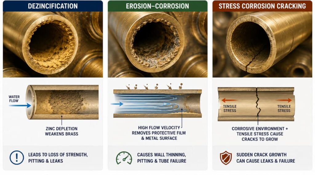
Dezincification Weakens Brass by Removing Zinc
Dezincification selectively removes zinc from brass, leaving porous copper with degraded mechanical properties. It is especially problematic in stagnant seawater or mildly acidic conditions.
Prevention:
- Specify inhibited admiralty brass with arsenic or antimony additions
- Maintain water velocity to avoid stagnant conditions
- Control pH within recommended ranges
- Use cathodic protection for critical applications
Erosion-Corrosion Occurs in High-Velocity Flow
Erosion-corrosion combines mechanical wear and electrochemical attack. It often occurs in high-velocity flows, especially where turbulence or particulates are present.
Prevention:
- Limit water velocity to alloy-specific maximums
- Design smooth flow paths without abrupt direction changes
- Filter particulates from cooling water
- Select aluminum brass for high-velocity seawater applications
Stress Corrosion Cracking Can Occur Around Ammonia
Ammonia and certain sulfur compounds can induce stress corrosion cracking in brass under tensile stress.
Prevention:
- Avoid ammonia-bearing atmospheres
- Stress-relieve components after fabrication
- Select alternative materials when ammonia exposure is unavoidable
How Can Brass Heat Exchanger Performance Be Optimised?
Engineers can optimise heat exchanger designs by using brass’s thermal properties strategically.
Higher Conductivity Supports Compact Designs
Brass thermal conductivity enables several design trade-offs:
- Compact heat exchangers achieving the same duty
- Closer approach temperatures
- Reduced tube count in suitable designs
Enhanced Surfaces Can Offset Conductivity Limits
Surface enhancements can compensate for conductivity limitations:
- Internally grooved tubes increase surface area and turbulence
- Corrugated tubes promote mixing without external fins
- Twisted tube inserts generate secondary flow patterns
Manufacturing must balance thermal benefits against production complexity, cost, and inspection requirements.
Brass Can Reduce Fouling Maintenance
Copper’s natural biofouling resistance gives brass several operational advantages:
- Reduced cleaning frequency compared to steel or aluminium in some water systems
- Lower chemical treatment requirements
- More stable performance over extended operating periods
Designers may still use conservative fouling factors, but brass can help maintain better long-term thermal performance in suitable applications.
Conclusion
Brass remains a valuable material for heat exchanger manufacturing because it combines practical thermal conductivity, good corrosion resistance, strong fabricability, and long service potential. While pure copper and aluminium offer higher conductivity, brass often delivers a better overall balance for marine, HVAC, condenser, and industrial cooling applications. The best alloy choice depends on the operating environment: standard brasses suit freshwater systems, admiralty brass balances conductivity and seawater resistance, and aluminum brass performs well in harsher marine conditions.
For engineers and sourcing teams, choosing a heat exchanger material is not only about conductivity. It also involves corrosion risk, manufacturing method, pressure requirements, joining quality, water chemistry, and long-term maintenance. Buyers comparing technical manufacturing partners rather than promotional products suppliers should prioritise proven alloy knowledge, process control, inspection capability, and practical design support.
At Align Manufacturing, we help customers turn engineered metal parts from print to reality across Southeast Asia, including Thailand, Vietnam, and India. Our experience across CNC machining, casting, stamping, forging, and fabrication allows us to support projects where material selection and process choice directly affect performance. For teams evaluating cast components, marine hardware, or industrial parts, our regional expertise also makes gravity casting in Vietnam a practical option for balancing quality, cost, and supply-chain flexibility.
Frequently Asked Questions
What brass alloy offers the best thermal conductivity for heat exchangers?
Standard brass alloys such as C26000 cartridge brass and C28000 Muntz metal offer some of the highest thermal conductivity values among common heat exchanger brasses, at around 120–125 W/m·K. However, they lack the corrosion resistance needed for seawater applications. For marine service, admiralty brass C44300 provides the best balance of thermal performance and corrosion resistance, while aluminum brass C68700 offers stronger corrosion resistance with lower conductivity.
How does brass thermal conductivity compare to copper and aluminum?
Pure copper has the highest conductivity at around 398 W/m·K. Aluminium is commonly around 205 W/m·K. Brass alloys are typically around 100–125 W/m·K, while stainless steel is much lower at around 15–25 W/m·K. Brass occupies a practical middle ground by offering better conductivity than stainless steel with stronger durability and corrosion performance than many alternatives in suitable water environments.
Why does thermal conductivity increase with temperature for brass?
In many brass alloys, thermal conductivity can increase as temperature rises due to changes in electron and lattice vibration interactions. This can benefit heat exchanger performance because conductivity may improve at higher operating temperatures, although engineers still need to calculate performance based on the actual service temperature range.
What causes brass heat exchanger tubes to fail prematurely?
Common failure modes include dezincification, erosion-corrosion, stress corrosion cracking, pitting corrosion, and fatigue from thermal cycling or vibration. Proper alloy selection, appropriate flow velocity, clean manufacturing, water treatment, and regular maintenance prevent most premature failures.
How do I select between admiralty brass and aluminum brass for marine heat exchangers?
Select admiralty brass C44300 when seawater velocity is moderate, sediment levels are low, cost optimisation is important, and service history supports satisfactory performance. Select aluminum brass C68700 when water velocity is high, sediment or abrasive particles are present, maximum service life is critical, or corrosion conditions are severe.
Can brass heat exchangers handle steam applications?
Yes. Brass heat exchangers are commonly used in steam heating and condensing applications. Admiralty brass performs well in surface condensers and steam heating systems. Important design considerations include pressure containment, condensate drainage, non-condensable gas venting, and compatibility with condensate chemistry.
What water chemistry conditions favour brass heat exchangers?
Brass performs best in neutral to mildly alkaline water, typically around pH 7.0–9.0, with low ammonia and controlled chloride levels. Aerated water can support protective oxide formation. Standard brasses should avoid high ammonia, high sulfides, and acidic conditions below pH 6.5.
How does fouling affect brass heat exchanger performance?
Brass offers natural biofouling resistance because of its copper content, reducing biological growth compared with steel or aluminium in some systems. Drawn brass tubes can also achieve smooth surfaces that reduce particulate adhesion. Mineral scaling can still occur, so water treatment and periodic cleaning may still be needed.
What manufacturing methods produce the best brass heat exchanger tubes?
Seamless extrusion followed by cold drawing is commonly used for high-quality heat exchanger tubes. This process eliminates weld seams, achieves tight tolerances, creates smooth surfaces, and provides uniform mechanical properties. ASTM B111 defines requirements for copper and copper-alloy seamless condenser tubes.
How do I calculate the heat transfer improvement from using brass instead of stainless steel?
The improvement depends on the controlling resistance. When tube wall conduction limits performance, the improvement can approximate the conductivity ratio between brass and stainless steel. In practical systems where convection often controls heat transfer, the improvement is less dramatic, but brass can still support higher U-values, smaller equipment size, or improved performance.
Can damaged brass heat exchanger tubes be repaired?
Yes. Individual tube replacement is the standard repair method for leaking tubes. Other methods include tube plugging, which reduces capacity, or local annealing for stress relief in limited areas. Heat exchangers should be designed with tube sheet layouts that allow inspection and tube replacement.
What is the maximum operating temperature for brass heat exchangers?
Brass heat exchangers typically operate below 200°C. Standard brasses such as C26000 and C27000 are often limited to around 150–175°C, admiralty brass C44300 to around 175–200°C, and aluminum brass C68700 to around 150–175°C. Above these ranges, strength decreases and corrosion rates may increase.
How does zinc content affect brass thermal conductivity?
Increasing zinc content generally lowers thermal conductivity compared with pure copper. Pure copper has around 398 W/m·K, while cartridge brass with roughly 30% zinc is closer to 123 W/m·K. Additional alloying elements such as tin and aluminum can further reduce conductivity, although exact values depend on alloy phase structure.
What brazing materials work best for brass heat exchanger assembly?
Silver-based brazing alloys, including BAg-1, BAg-5, and BAg-7 under AWS A5.8, are commonly used for brass heat exchanger assembly. They provide strong joints, good flow characteristics, and corrosion-resistant performance when paired with proper flux selection, joint design, and temperature control.
Are there environmental concerns with brass heat exchangers?
Brass contains copper and zinc, while some alloys include small additions of arsenic, tin, or aluminum. Environmental considerations include copper release in sensitive waters and responsible handling of alloying elements during manufacturing. However, brass is highly recyclable and can offer a favourable environmental profile because of its long service life and full recyclability.
Risk Priority Number (RPN) Calculation and Mitigation Strategies

Manufacturing organisations face constant pressure to identify and eliminate potential failures before they reach customers. Failure Mode and Effects Analysis (FMEA) provides a systematic framework for proactive risk management, with the Risk Priority Number (RPN) serving as the quantitative engine behind prioritisation decisions. Understanding RPN calculation and, more importantly, its strategic application for risk mitigation, separates organisations that merely document risks from those that systematically reduce them.
This guide examines traditional RPN methodology and the evolving AIAG-VDA approach, providing manufacturing engineers, quality professionals, and operations managers with practical tools for effective risk-based decision-making.
What Are FMEA and Risk Priority Numbers?
FMEA systematically examines potential failure modes in products, processes, or systems, evaluates their effects, and supports preventive action planning. The methodology originated in aerospace and defence during the 1940s, expanded through automotive manufacturing, and now applies across many manufacturing sectors.
FMEA Provides a Structured Risk Framework
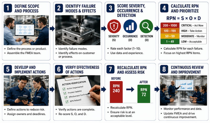
Effective FMEA implementation follows a clear progression:
- Scope definition: Establish analysis boundaries and objectives
- Structure analysis: Break down the product or process into analysable elements
- Function analysis: Define what each element must accomplish
- Failure analysis: Identify how functions might fail and what effects may result
- Risk analysis: Evaluate and prioritise risks using RPN or Action Priority
- Optimisation: Implement actions to reduce risk and verify effectiveness
RPN calculation occurs during risk analysis, providing a numerical basis for prioritising improvement efforts among many potential failure modes.
How Is Traditional RPN Calculated?
The classic RPN calculation multiplies three factors:
RPN = Severity (S) × Occurrence (O) × Detection (D)
Each factor is rated on a scale of 1 to 10, producing RPN values from 1, the lowest risk, to 1,000, the highest risk.
| Factor | Scale | Assessment Basis |
| Severity (S) | 1-10 | Impact on customer or end user if the failure occurs |
| Occurrence (O) | 1-10 | Likelihood that the cause will occur |
| Detection (D) | 1-10 | Ability to detect the cause or failure mode before impact |
How Should Severity, Occurrence, and Detection Be Scored?
Each scoring factor measures a different aspect of risk. Consistent interpretation is essential because inconsistent ratings can make RPN values misleading.
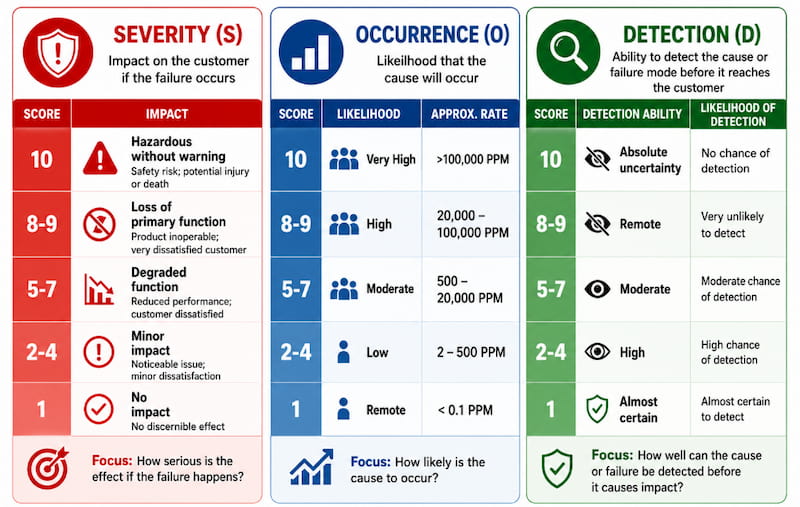
Severity Measures the Impact of Failure
| Rating | Description | Examples |
| 10 | Hazardous without warning | Safety risk without notice; potential injury or death |
| 9 | Hazardous with warning | Safety risk with warning; potential injury or death |
| 8 | Loss of primary function | Primary function inoperable; customer very dissatisfied |
| 7 | Degraded primary function | Reduced performance; customer dissatisfied |
| 6 | Loss of secondary function | Comfort or convenience function inoperable |
| 5 | Degraded secondary function | Reduced comfort or convenience performance |
| 4 | Minor nuisance | Minor issue noticed by most customers |
| 3 | Very minor | Minor issue noticed by selective customers |
| 2 | Incidental | Slight annoyance |
| 1 | None | No discernible effect |
Occurrence Measures the Likelihood of Failure
| Rating | Probability | PPM Approx. | Description |
| 10 | Very high | >100,000 | Failure almost inevitable |
| 9 | High | 50,000 | Repeated failures likely |
| 8 | High | 20,000 | Frequent failures |
| 7 | Moderate | 10,000 | Occasional failures |
| 6 | Moderate | 2,000 | Infrequent failures |
| 5 | Moderate | 500 | Relatively few failures |
| 4 | Low | 100 | Isolated failures |
| 3 | Low | 20 | Few failures |
| 2 | Low | 2 | Very few failures |
| 1 | Remote | <0.1 | Failure unlikely |
Detection Measures the Ability to Find a Failure Before Impact
| Rating | Detection Likelihood | Description |
| 10 | Absolute uncertainty | No detection opportunity; no controls |
| 9 | Very remote | Unlikely to detect with current controls |
| 8 | Remote | Poor detection with current controls |
| 7 | Very low | Low likelihood of detection |
| 6 | Low | Moderate detection capability |
| 5 | Moderate | Moderate detection with established controls |
| 4 | Moderately high | Good detection with established controls |
| 3 | High | High likelihood of detection |
| 2 | Very high | Very high likelihood of detection |
| 1 | Almost certain | Almost certain detection with reliable controls |
Important: Detection ratings assess the likelihood of detecting the cause or failure mode, not the effectiveness of controls in preventing occurrence. A detection rating of 1 indicates almost certain detection before impact, while 10 indicates no meaningful opportunity for detection.
What Are Practical RPN Calculation Examples?
Practical examples show how RPN applies across manufacturing scenarios.
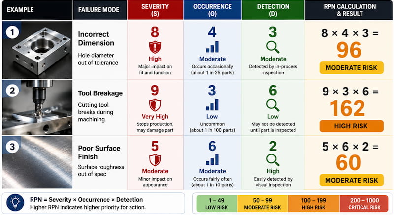
Example 1: Machined Brass Component
Failure Mode: Dimensional variation in critical sealing surface
Effect: Fluid leakage; potential equipment damage
| Factor | Rating | Justification |
| Severity | 8 | Primary function loss; customer dissatisfied |
| Occurrence | 4 | Process capability study shows 100 PPM |
| Detection | 3 | In-process CMM inspection catches defects |
| RPN | 96 | 8 × 4 × 3 = 96 |
With an RPN of 96, this failure mode warrants attention, although it may not be the highest priority depending on other identified risks. For brass components, material grade, machinability, and inspection strategy should be reviewed alongside the relevant brass material specifications before finalising risk controls.
Example 2: Welded Assembly
Failure Mode: Incomplete weld penetration
Effect: Structural failure under load; potential safety hazard
| Factor | Rating | Justification |
| Severity | 9 | Hazardous with warning; safety risk |
| Occurrence | 6 | Infrequent but documented failures |
| Detection | 5 | Visual inspection; some defects may escape |
| RPN | 270 | 9 × 6 × 5 = 270 |
An RPN of 270 indicates high priority for risk reduction action.
Example 3: Electronic Assembly
Failure Mode: Solder joint fracture
Effect: Intermittent electrical connection; difficult to diagnose
| Factor | Rating | Justification |
| Severity | 6 | Secondary function degraded |
| Occurrence | 3 | Few failures historically |
| Detection | 8 | Difficult to detect during production testing |
| RPN | 144 | 6 × 3 × 8 = 144 |
Detection weakness, rated 8, drives the RPN despite relatively low occurrence. Improvement should focus on stronger detection controls or process controls that prevent occurrence.
What RPN Thresholds Should Manufacturers Use?
Organisations establish RPN thresholds to guide action decisions. These thresholds should reflect industry requirements, regulatory expectations, customer requirements, and internal risk tolerance.
Absolute Threshold Method
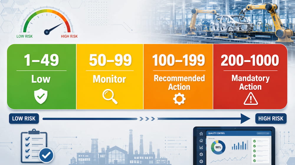
| RPN Range | Action Required | Timeline |
| 200-1000 | Mandatory action | Immediate |
| 100-199 | Recommended action | Next review cycle |
| 50-99 | Consider action | As resources allow |
| 1-49 | Acceptable risk | Monitor |
Relative Priority Method
Rank all identified failure modes by RPN and address:
- Top 20% highest RPN values
- Any failure mode with severity rating ≥ 8, regardless of RPN
- Any failure mode with occurrence × severity product ≥ 40
Severity-Dominant Method
Critical failures with severity ratings of 9-10 require mandatory action regardless of RPN. This approach recognises that low-probability, high-consequence events still demand attention even when the calculated RPN appears moderate.
Recommended practice: Establish organisational thresholds based on industry norms, regulatory requirements, and risk tolerance, but always require action for severity 9-10 failure modes.
What Is the AIAG-VDA FMEA Standard?
According to the AIAG-VDA FMEA Handbook, 1st Edition, released in 2019, the updated methodology introduced significant changes, including replacing traditional RPN with Action Priority (AP). Organisations transitioning between standards should understand both approaches.
Action Priority Classifies Risk Into Clear Categories
The AP system classifies risk into three categories:
H, High Priority: The team must identify appropriate action to improve prevention and/or detection controls, or justify why current controls are adequate.
M, Medium Priority: The team should identify appropriate action to improve prevention and/or detection controls, or justify why current controls are adequate.
L, Low Priority: The team could identify action to improve prevention and/or detection controls.
AP Determination Matrix
| Severity | Occurrence | Detection | Action Priority |
| 9-10 | 8-10 | 8-10 | H |
| 9-10 | 8-10 | 1-7 | H |
| 9-10 | 1-7 | 8-10 | H |
| 9-10 | 1-7 | 1-7 | M |
| 5-8 | 8-10 | 8-10 | H |
| 5-8 | 8-10 | 1-7 | M |
| 5-8 | 1-7 | 8-10 | M |
| 5-8 | 1-7 | 1-7 | L |
| 1-4 | Any | Any | L |
How Do RPN and Action Priority Compare?
| Aspect | Traditional RPN | AIAG-VDA AP |
| Output | Numeric value from 1-1000 | Categorical: H, M, or L |
| Severity emphasis | Equal weighting | High severity drives priority |
| Resolution | Distinguishes subtle differences | Provides clear action categories |
| Ranking | Continuous scale | Tiered priority bands |
| Industry adoption | Established and widely used | Growing, especially in automotive |
Organisations should evaluate which approach aligns with customer requirements and internal quality systems. Many companies maintain capability with both methodologies.
How Can Manufacturers Reduce RPN?
Effective risk reduction targets the underlying factors driving RPN elevation.
Severity Reduction Requires Design or Specification Changes
Severity reductions typically require changes to design intent, product specifications, or system safeguards.
Design modifications may include:
- Redundancy for critical functions
- Fail-safe design
- Derating components below maximum specifications
- Material upgrades for critical applications
- Simplification to reduce potential failure points
Warning systems may include:
- Early warning indicators for degradation
- Interlocks preventing operation outside safe parameters
- Monitoring systems detecting early failure signs
Consequence mitigation may include:
- Containment systems limiting failure propagation
- Damage-limiting designs with controlled failure modes
- Emergency shutdown systems
Occurrence Reduction Improves Process Control
Occurrence reductions focus on process control, prevention, and error-proofing.
Error-proofing, also known as poka-yoke, may include:
- Physical devices preventing incorrect assembly
- Sensors detecting missing components
- Interlocks ensuring complete operations
- Gauges confirming correct setup
Process control may include:
- Statistical process control monitoring
- Automated process parameter control
- Preventive maintenance to reduce variability
- Supplier quality management
Design for manufacturability may include:
- Tolerance optimisation
- Simplified assembly sequences
- Reduced component counts
- Robust design that allows controlled process variation
Detection Improvement Strengthens Inspection and Testing
Detection improvements enhance inspection and testing effectiveness.
In-process inspection may include:
- Automated vision systems
- Sensor-based monitoring
- Statistical sampling plans
- Real-time dimensional measurement
Testing enhancements may include:
- Accelerated life testing
- Environmental stress screening
- Functional testing at boundary conditions
- Burn-in for early failure identification
Traceability systems may include:
- Lot tracking for targeted containment
- Serialization for individual component traceability
- Process data collection and analysis
- Digital thread connection from design to production
For surface-related failure risks, such as scratches, corrosion exposure, coating defects, or cosmetic non-conformance, manufacturers should also assess whether the selected brass surface finish supports both functional and aesthetic requirements.
How Is RPN Implemented in Manufacturing?
Successful RPN implementation requires systematic process integration across design, production, quality, and management review.
PFMEA Identifies Process Risks Before Production
Process FMEA, or PFMEA, analyses manufacturing processes to identify potential failures before production begins. For CNC parts, a focused brass-specific PFMEA for CNC operations can help teams account for material behaviour, burr formation, tool wear, dimensional drift, and inspection controls more accurately than a generic template.
PFMEA timing:
- Initial PFMEA: During process development, before tooling procurement
- Update 1: After prototype build, incorporating learning
- Update 2: After pilot production, using process validation data
- Ongoing: Continuous updates as changes occur
Key PFMEA elements:
- Process step or operation identification
- Potential failure modes, or how the process could fail
- Potential failure effects on downstream operations and customers
- Potential causes explaining why the failure may occur
- Current prevention and detection controls
- RPN calculation and action prioritisation
- Action implementation and RPN recalculation
A clear process flow diagram for CNC machining also supports PFMEA by mapping each operation before risk scoring begins.
DFMEA Identifies Product Design Risks Early
Design FMEA, or DFMEA, analyses product designs to identify potential failures before manufacturing begins.
DFMEA focus areas include:
- Functional requirements and potential failures
- Interface analysis between components and subsystems
- Material and manufacturing feasibility
- Service and maintenance considerations
- End-of-life and recycling requirements
Design changes that reduce severity are usually most cost-effective when implemented during the design phase, before manufacturing commitment.
How Should RPN Be Tracked and Managed?
Effective RPN management requires systematic tracking, ownership, and review.
RPN Reduction Targets Keep Risk Visible
Organisations should:
- Establish clear RPN reduction goals, such as “no failure modes with RPN > 100”
- Track RPN reduction as actions are implemented
- Monitor residual risk after mitigation actions
- Verify whether implemented controls actually reduce risk
Management Review Prevents Stalled Actions
Management review should include:
- FMEA status in quality management reviews
- Regular review of high RPN items and action progress
- Escalation of stalled actions to the appropriate management level
- Review of recurring failure modes using updated production and field data
Software Tools Support FMEA Control
Software options include:
- Excel templates for basic FMEA management
- Dedicated FMEA software such as IQ-RM, APICS eFMEA, PLATO e1ns, and ReliaSoft XFMEA
- PLM integration for design FMEA linkage
- ERP integration for process control tracking
What Are Common RPN Implementation Pitfalls?
Organisations often encounter challenges when implementing RPN-based risk management.
Scoring Inconsistency Weakens Comparability
Different teams may apply rating scales inconsistently.
Symptoms include:
- Similar risks receiving different ratings across teams
- RPN values not correlating with actual field performance
- Difficulty comparing risk across different FMEAs
Solutions include:
- Develop organisational rating guidelines with specific examples
- Calibrate teams through cross-functional reviews
- Use anchor products or processes as reference benchmarks
- Provide regular training on rating criteria
Detection Rating Confusion Creates Misleading Scores
Teams frequently misunderstand detection ratings.
Common error: Rating detection based on how well a control prevents occurrence, rather than how likely it is to detect the cause or failure mode.
Correction: Detection ratings assess only the likelihood of detecting the cause or failure mode before impact. Prevention controls, which reduce occurrence, are rated separately.
Overemphasis on RPN Numbers Can Obscure Real Risk
A purely numerical focus can lead teams to optimise for RPN reduction without fully understanding the risk.
Better practice: Use RPN as a prioritisation tool, but require a narrative description of the risk and the rationale for action. High-severity items demand action regardless of calculated RPN.
Inadequate Action Implementation Limits Risk Reduction
Identified actions may fail to achieve the intended reduction.
Root causes include:
- Actions not implemented as specified
- Actions ineffective for the stated purpose
- RPN recalculation being too optimistic without verification
Preventive measures include:
- Require action validation before reducing RPN
- Verify implementation through audit
- Track actual performance against predicted occurrence
How Is RPN Applied Across Different Industries?
Different industries apply RPN with sector-specific adaptations.
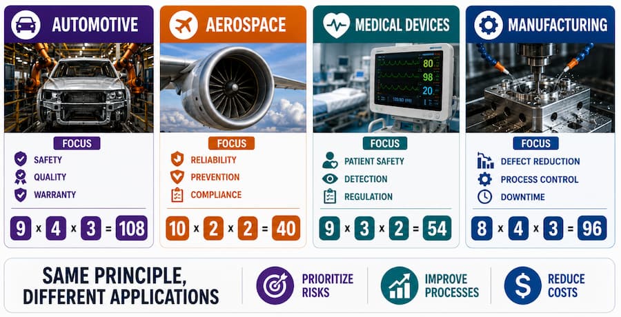
Automotive FMEA Supports IATF 16949 Requirements
Automotive FMEA requirements under IATF 16949 often include:
- AIAG-VDA methodology for many OEM requirements
- Special characteristics classification, such as Critical, Significant, or Major
- Control Plan linkage to FMEA
- Regular review and updates based on field performance
- Customer-specific requirement integration
Automotive severity ratings emphasise safety and regulatory compliance, with severity 10 reserved for safety risks without warning.
Aerospace FMEA Prioritises Flight Safety
Aerospace FMEA, including applications aligned with AS9145 practices, emphasises:
- Rigorous severity assessment due to flight safety implications
- Extensive detection controls, including non-destructive testing
- Certification and regulatory compliance integration
- Long service life and mission-critical function consideration
Aerospace organisations typically use more conservative RPN thresholds because failure consequences can be severe.
Medical Device FMEA Integrates With ISO 14971
According to ISO 14971 guidance for medical device risk management, FMEA may be integrated into a broader risk management process that considers patient harm, regulatory requirements, and post-market surveillance.
Medical device risk management commonly includes:
- Risk acceptability criteria based on patient harm severity
- Regulatory submission requirements for risk analysis
- Post-market surveillance to update risk assessments
- Biological safety and usability risk integration
Medical device FMEA often requires stronger detection and verification controls for patient-contacting features.
Conclusion
RPN remains a practical and widely understood method for prioritising manufacturing risk, especially when teams apply severity, occurrence, and detection ratings consistently. While the AIAG-VDA Action Priority approach provides clearer action categories and stronger severity emphasis, traditional RPN still plays an important role in many quality systems, legacy processes, and supplier quality programmes. The most effective organisations use these tools not just to score risk, but to guide prevention, improve detection, and verify that mitigation actions genuinely reduce failure potential.
At Align Manufacturing, we approach risk management as part of building reliable, production-ready manufacturing systems, from CNC machining and casting to supplier quality and process validation. When customers evaluate manufacturing partners, whether they are sourcing industrial components, looking for specialist production support, or comparing promotional products suppliers for broader procurement needs, structured quality methods such as FMEA help separate capable suppliers from reactive ones. For projects involving gravity casting Vietnam, Align Manufacturing applies manufacturing experience, process control, and practical risk reduction to help customers move from design intent to dependable production outcomes.
Frequently Asked Questions
What Is the Difference Between RPN and Action Priority?
RPN provides a numeric score from 1 to 1,000 by multiplying Severity × Occurrence × Detection. Action Priority classifies risk into High, Medium, or Low categories using a matrix based on the same three factors. AP places greater emphasis on severity and is the newer AIAG-VDA standard, while RPN remains widely used in legacy systems and other industries.
What RPN Threshold Requires Mandatory Action?
Most organisations set mandatory action thresholds between 100 and 200, but practices vary. More important than the absolute threshold is consistent application and mandatory action for severity 9-10 failure modes regardless of RPN. Thresholds should reflect industry benchmarks, regulatory requirements, customer expectations, and internal risk tolerance.
Can RPN Compare Risks Across Different Products or Processes?
Direct RPN comparison across different FMEAs requires caution. Rating scales may be applied differently by different teams, and severity context varies by application. Comparisons work best within a single FMEA or when teams have been calibrated to apply ratings consistently.
Why Does the Same Failure Mode Have Different RPN Values in Different FMEAs?
The same failure mechanism may have different RPN values because context matters. A sealing failure might have severity 4 in a non-critical consumer application but severity 9 in a medical device or aerospace system. Occurrence and detection ratings also vary based on each process and its controls.
How Do I Reduce RPN Most Effectively?
Focus on severity reduction first when possible through design changes, then occurrence reduction through process controls and error-proofing. Detection improvements help identify failures earlier, but they do not reduce the actual failure rate. Occurrence reduction through prevention controls usually provides stronger long-term improvement than inspection alone.
Should We Use RPN or AP for FMEA Implementation?
The choice depends on customer requirements and organisational preference. Automotive suppliers serving IATF 16949 customers often need AIAG-VDA AP methodology. Organisations without specific customer mandates may choose either approach. Many maintain capability with both to support different customer requirements.
What Is the Most Common Mistake in RPN Calculation?
The most common error is detection rating confusion. Teams may rate detection based on how well a control prevents occurrence, instead of how likely it is to detect the cause or failure mode before impact. Another frequent issue is inconsistent scoring between teams or FMEAs.
How Often Should FMEA and RPN Be Updated?
Update FMEA when new failure modes are identified, design or process changes occur, new information about failure mechanisms becomes available, customer complaints or warranty data indicate gaps, or periodic review cycles trigger reassessment. Critical processes are often reviewed at least annually.
Can RPN Be Zero?
No. RPN cannot be zero because the minimum rating for each factor is 1. The lowest possible RPN is 1, calculated as 1 × 1 × 1. In practice, organisations rarely see very low RPN values because even minor issues usually score above 1 in at least one category.
How Do I Handle Failure Modes With the Same RPN?
Use secondary criteria for prioritisation. Higher severity should take precedence. If severity is equal, consider higher occurrence, business impact, customer visibility, warranty cost, and ease of implementation. Some organisations also use Severity × Occurrence as a secondary ranking metric.
What Role Does RPN Play in Control Plans?
Control Plans document the prevention and detection controls identified in FMEA. High RPN items usually drive more robust controls, such as special characteristics classification, frequent inspection, SPC application, error-proofing devices, and reaction plans when controls indicate potential issues.
Is RPN Applicable to Service or Software Processes?
Yes. FMEA methodology can be adapted to service and software processes, although rating scales need contextual adjustment. Severity may assess business impact or customer dissatisfaction, occurrence may relate to process failure rates, and detection may consider review, testing, or monitoring effectiveness.
How Do I Get Started With FMEA and RPN?
Start with a pilot project on a critical process or product. Form a cross-functional team, select the appropriate FMEA type, apply the methodology carefully, implement actions for the highest-risk items, document lessons learned, and expand to additional processes based on results.
What Software Tools Support RPN Calculation and FMEA Management?
Options range from Excel templates to dedicated FMEA software such as IQ-RM, APICS eFMEA, PLATO e1ns, and ReliaSoft XFMEA. PLM and quality management systems may also include FMEA modules. Selection criteria should include usability, reporting, integration, collaboration features, and cost.
How Does RPN Relate to Six Sigma DMAIC?
In Six Sigma DMAIC, FMEA and RPN are often used in the Analyse phase to identify and prioritise potential root causes or failure modes. Risk analysis informs the Improve phase, while Control Plans linked to FMEA support the Control phase.
Brass Material Specifications: Understanding UNS, DIN, and ISO Standards

According to Mordor Intelligence, the global brass market is projected to reach USD 15.28 billion by 2034, growing at a 5.0% CAGR from its 2025 valuation of USD 9.82 billion. For engineers, procurement managers, and manufacturers working with brass components, understanding material specifications is not merely academic. It directly impacts product performance, regulatory compliance, and supply chain efficiency.
Brass material specifications span multiple international standards systems, each with its own numbering conventions and classification methods. At Align Manufacturing, we work with these specifications in practical sourcing and production environments, where the correct alloy designation can affect machining performance, inspection requirements, and final part quality.
This guide explains UNS, DIN, EN, and ISO standards, providing practical cross-reference tools and selection guidance for real-world engineering decisions.
What Is Brass and Why Do Standards Matter?
Brass is a copper-zinc alloy that typically contains 60% to 95% copper, with zinc making up the remainder, according to the Copper Development Association. The ratio of copper to zinc determines the alloy’s properties, from ductility and corrosion resistance to machinability and strength. Small additions of lead, tin, aluminium, or other elements further modify these characteristics for specific applications.
Material standards exist to ensure consistency, interoperability, and safety across global supply chains. When an engineer specifies UNS C36000 or DIN CuZn39Pb3, they are communicating precise chemical composition and mechanical property requirements. Understanding how these designations relate across different standards systems prevents costly procurement errors and ensures components meet performance expectations regardless of geographic origin.
For buyers comparing brass against other copper-based materials, our brass vs. bronze manufacturing guide can also help clarify where each alloy family makes sense.
What Does UNS Stand for in Brass Specifications?
UNS stands for Unified Numbering System, a North American standard administered by the Copper Development Association and ASTM International. The UNS provides a consistent designation system for metals and alloys across the United States and Canada, with widespread adoption in global supply chains.
Different regions use different brass standards because national and regional standards bodies developed separately over time. North America predominantly uses UNS, Europe uses DIN and EN standards, while ISO provides international frameworks. As global sourcing has expanded, cross-referencing between these systems has become increasingly important.
How Does the UNS Numbering System Work?
The Unified Numbering System organises copper alloys into logical categories based on composition and form. For brass specifically, understanding these number ranges enables engineers to quickly identify alloy families and their general characteristics.
Wrought and Cast Brass Use Different Number Ranges
UNS distinguishes between wrought and cast brass alloys through number ranges:
| Category | UNS Range | Description |
| Wrought brass alloys | C20000 to C49999 | Worked brass alloys used for sheet, strip, rod, bar, and formed products |
| Cast brass alloys | C83300 to C89999 | Cast brass alloys used for components made through casting processes |
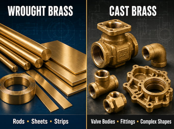
Wrought brass alloys include:
- C20000 to C29999: copper-zinc alloys, also known as binary brasses
- C30000 to C39999: copper-zinc-lead alloys, also known as leaded brasses
- C40000 to C49999: copper-zinc-tin alloys, also known as tin brasses
Cast brass alloys include:
- C83300 to C84999: cast copper-zinc alloys
- C85000 to C89999: cast copper-zinc-lead and special brasses
This distinction matters because cast and wrought alloys have different mechanical properties, even with similar chemical compositions. Cast alloys typically have lower ductility but can achieve complex geometries that may be difficult or impossible with wrought materials.
UNS Numbers Give Quick Alloy Clues
Each UNS number provides immediate clues about alloy composition:
- C26000: cartridge brass, approximately 70% copper and 30% zinc
- C36000: free-cutting brass, approximately 61.5% copper, 35.5% zinc, and 3% lead
- C46400: naval brass, approximately 60% copper, 39% zinc, and 1% tin
The UNS does not encode exact composition percentages. Engineers must consult datasheets or standards for precise values. However, the numbering patterns help engineers quickly identify alloy families during initial material selection.
For machining-focused projects, our brass alloy guide for machining gives a deeper comparison of grades such as C360, C464, and other commonly specified brass alloys.
What Is the Difference Between C260 and C360 Brass?
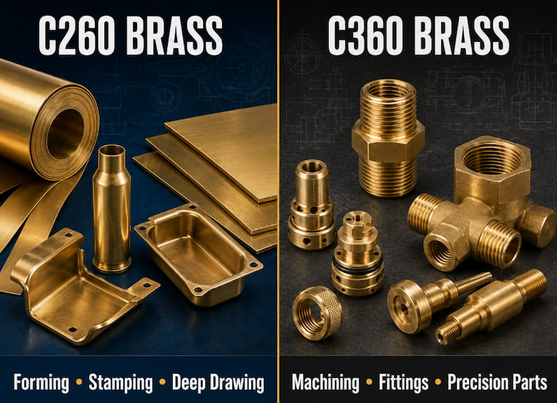
C26000, also known as cartridge brass, contains approximately 70% copper and 30% zinc. It offers excellent ductility for cold working applications such as ammunition casings, heat exchangers, and formed components.
C36000, also known as free-cutting brass, contains approximately 61.5% copper, 35.5% zinc, and 3% lead. It provides superior machinability but limited cold formability, making it ideal for high-speed screw machine products, fittings, and precision machined parts.
The “C” prefix in UNS brass designations refers to copper and copper alloys. This distinguishes brass, bronze, and copper alloy grades from other metal systems.
How Do European DIN and EN Brass Standards Work?
European brass specifications operate under two primary frameworks: DIN standards and EN standards. DIN refers to Deutsches Institut für Normung, historically the German national standards system. EN standards are European Norms maintained by CEN, the European Committee for Standardization.
DIN Material Numbers Describe Copper Alloy Families
DIN uses a material number system, also known as Werkstoffnummer, with the format 2.0XXX for copper alloys:
| DIN Range | Alloy Family |
| 2.02XX | Binary copper-zinc alloys |
| 2.03XX | Leaded copper-zinc alloys |
| 2.04XX | Special brasses |
| 2.05XX | Tin brasses |
Common DIN material numbers include:
- 2.0265: CuZn30, cartridge brass equivalent
- 2.0321: CuZn37, general-purpose brass
- 2.0401: CuZn39Pb3, free-cutting brass equivalent
- 2.0375: CuZn36Pb2As, DZR brass
The chemical formula format, such as CuZn30 or CuZn39Pb3, explicitly states the composition. This makes DIN designations more descriptive than UNS numbers for engineers familiar with alloy chemistry.
EN Codes Identify Product Type and Alloy Group
EN standards use a six-character alphanumeric code:
C + W/B/C/M + three digits + letter
Common prefixes include:
- CW: wrought products
- CB: ingot for casting
- CC: cast products
Brass number ranges within the EN system include:
- CW500L to CW549L: copper-zinc alloys
- CW600N to CW649N: copper-zinc-lead alloys
- CW700R to CW749R: copper-zinc complex alloys
Examples include:
- CW505L: CuZn30, equivalent to C26000
- CW603N: CuZn39Pb3, equivalent to C36000
- CW712R: CuZn38Sn1, naval brass equivalent
Temper Designations Define Mechanical Condition
European standards specify mechanical properties through temper designations:
| Temper Designation | Meaning |
| R | As drawn or rolled |
| H | Hard temper |
| Y | As extruded |
| M | As manufactured |
Suffix numbers indicate specific strength ranges. For example, R250 means 250 MPa minimum tensile strength, while H04 indicates a hard temper with specific hardness requirements.
What Does CW508L Mean in Brass Designation?
CW508L is an EN designation for CuZn37, a common general-purpose brass containing approximately 63% copper and 37% zinc. The “CW” indicates wrought product, “508” is the specific alloy code, and “L” denotes the material group within copper-zinc alloys.
To convert UNS to DIN or EN numbers, engineers usually cross-reference composition equivalence. For example, UNS C36000 corresponds to DIN 2.0401, DIN CuZn39Pb3, and EN CW603N.
What ISO Standards Apply to Brass?
The International Organization for Standardization provides frameworks that bridge regional standards, enabling global trade and technical cooperation.
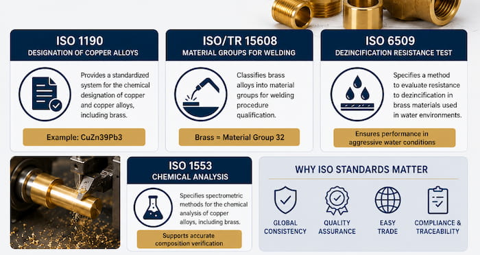
ISO 1190 Uses Chemical Designations
ISO 1190 Part 1 establishes a compositional designation system for copper alloys. The format uses chemical symbols with percentage indicators:
- CuZn38Pb2: copper-zinc alloy with 38% zinc and 2% lead
- CuZn37: binary copper-zinc alloy with 37% zinc
- CuZn40Mn1Pb1: complex brass with manganese and lead additions
This system is chemically descriptive, similar to DIN, making it intuitive for engineers familiar with alloy chemistry.
ISO Material Groups Support Welding and Fabrication
ISO/TR 15608 categorises materials into groups for welding and fabrication purposes. Brass alloys fall into Material Group 32:
| ISO Group | Brass Type |
| Group 32.1 | Alpha brasses with less than 37% zinc |
| Group 32.2 | Alpha-beta or duplex brasses with 38% to 42% zinc |
This classification matters for welding procedures, as alpha and alpha-beta brasses have different welding characteristics and require different process parameters.
ISO Testing Standards Help Verify Brass Performance
ISO maintains testing standards relevant to brass specification, including:
- ISO 6509: dezincification resistance testing
- ISO 1190: designation system for copper alloys
- ISO 1553: spectroscopic analysis for unalloyed copper and copper alloys
These standards support consistent testing and reporting of material properties across international supply chains.
What Is the Difference Between Alpha and Alpha-Beta Brass?
Alpha brasses contain less than 37% zinc and have a single-phase microstructure. They offer excellent cold working properties and are commonly used for forming, bending, and drawing.
Alpha-beta brasses, also called duplex brasses, contain approximately 38% to 42% zinc. They have a two-phase microstructure, giving them higher strength but reduced cold ductility. These alloys are better suited for hot working and casting applications.
What Are Common UNS, DIN, EN, and ISO Brass Equivalents?
The following tables provide practical cross-references for commonly specified brass alloys.
Common Brass Grades and International Equivalents
| Alloy Type | UNS | EN | DIN | JIS | Material No. |
| Free-cutting brass | C36000 | CuZn39Pb3 / CW603N | CuZn39Pb3 | C3604 | 2.0401 |
| Forging brass | C37700 | CuZn39Pb2 / CW612N | CuZn39Pb2 | C3771 | 2.0380 |
| Cartridge brass | C26000 | CuZn30 / CW505L | CuZn30 | C2600 | 2.0265 |
| Naval brass | C46400 | CuZn38Sn1 / CW712R | CuZn38Sn1 | C4640 | Not specified |
| Lead-free brass | C27450 | CuZn39Pb0.5 / CW610N | CuZn39Pb0.5 | Not specified | Not specified |
| DZR brass | Not specified | CW602N | CuZn36Pb2As | Not specified | 2.0375 |
| High tensile brass | C67500 | CW721R | CuZn40Mn1Pb1AlFeSn | Not specified | Not specified |
Brass Applications by Grade
| Application | Recommended Grades | Key Properties |
| Machining and screw machine work | C36000, C37700 | Excellent machinability |
| Plumbing fittings | C27450, CW602N | Corrosion resistance, lead-free options |
| Electrical connectors | C26000, C27000 | Good conductivity and formability |
| Marine hardware | C46400, C46500 | Seawater corrosion resistance |
| Decorative and architectural parts | C26000, C27000 | Colour and polishability |
| Automotive components | C36000, C37700 | Machinability and strength |
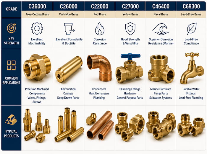
Chemical Composition Ranges
| Grade | Cu % | Zn % | Pb % | Sn % | Other |
| C26000 | 68.5 to 71.5 | Remainder | ≤0.07 | Not specified | Not specified |
| C36000 | 60.0 to 63.0 | Remainder | 2.5 to 3.7 | Not specified | Fe ≤0.35 |
| C46400 | 59.0 to 62.0 | Remainder | ≤0.20 | 0.50 to 1.00 | Not specified |
| C37700 | 58.0 to 61.0 | Remainder | 1.5 to 2.5 | Not specified | Fe ≤0.30 |
What Is Equivalent to UNS C36000 Brass?
UNS C36000, also known as free-cutting brass, is commonly equivalent to EN CW603N, DIN CuZn39Pb3, JIS C3604, and material number 2.0401.
These equivalents are useful for procurement teams sourcing across regions. However, final approval should always be based on the exact standard, chemical composition range, mechanical properties, and compliance requirements listed in the purchase specification.
When documentation control is critical, material equivalents should also be supported by certificates, traceability records, and controlled specification revisions. Our guide to manufacturing documentation control and material traceability explains how these records support quality assurance across suppliers.
What Is Dezincification Resistant Brass?
Dezincification resistant brass, or DZR brass, contains small arsenic or antimony additions, typically around 0.02% to 0.15%. These additions help inhibit selective leaching of zinc in water environments.
CW602N, also known as CuZn36Pb2As, is a common DZR grade used for plumbing fittings in aggressive water conditions.
How Do You Select the Right Brass for Your Application?
Material selection requires balancing mechanical requirements, manufacturing processes, environmental exposure, regulatory compliance, and cost.
High-Speed Machining Requires Free-Cutting Brass
C36000 free-cutting brass offers excellent machinability and is commonly used for threaded fittings, valves, and precision components. Its lead content provides lubrication during cutting, helping produce small, brittle chips that break cleanly. This supports longer tool life and faster production on screw machines.
For buyers evaluating part tolerances, surface finish, and production method, our guide on what CNC machining is explains how computer-controlled machining produces precision parts to exact specifications.
Cold Forming and Stamping Require Ductile Brass
C26000 cartridge brass provides excellent ductility for deep drawing, bending, and stamping operations. Its single-phase alpha microstructure allows significant deformation without cracking.
Corrosion-Resistant Applications Require Special Brass Grades
C46400 naval brass contains tin, which improves seawater corrosion resistance. DZR grades such as CW602N help prevent dezincification in potable water systems and aggressive water conditions.
Lead-Free Requirements Need Compliant Brass Alternatives
C27450 and similar low-lead alloys are used for potable water applications where lead content restrictions apply. Engineers should verify compliance with relevant standards such as NSF/ANSI 61 and applicable drinking water regulations before specifying materials.
For projects affected by lead restrictions, our guide to lead-free brass standards for manufacturing explains how regulatory changes influence alloy choice and supplier qualification.
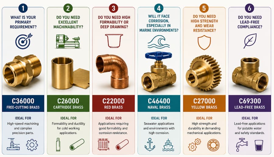
What Regulations Affect Brass Selection?
Brass selection may need to consider drinking water, electronics, consumer product, and regional compliance requirements.
NSF/ANSI 61 Applies to Drinking Water Components
Drinking water system components require strict control of lead content. For potable water applications, engineers should verify that the selected brass alloy meets NSF/ANSI 61 and applicable Safe Drinking Water Act requirements.
RoHS and REACH Affect EU Market Access
European regulations such as RoHS and REACH restrict hazardous substances in electrical, electronic, and consumer products. Engineers must verify compliance when specifying leaded brasses for EU markets.
Proposition 65 May Affect Consumer Products in California
California Proposition 65 requires warnings for products containing certain listed substances, including lead. Alternative alloys, protective coatings, or product warnings may be required depending on the application and market.
Which Brass Temper Should You Specify?
Temper designation indicates mechanical properties and formability.
| Temper | Best Use |
| Soft annealed, O | Maximum ductility for severe forming |
| Quarter hard, H01 | Moderate strength with good formability |
| Half hard, H02 | Balanced strength and formability |
| Full hard, H04 | Higher strength with limited formability |
| Spring, H08 | Highest strength for spring applications |
Specify soft annealed temper for severe forming operations. Use a half-hard temper for general-purpose applications requiring moderate strength. Specify full-hard or spring temper for components requiring maximum strength with minimal forming.
When Should You Choose C36000 Over C26000 Brass?
Choose C36000 for applications requiring extensive machining, such as threaded fittings, valves, and precision components. Its lead content improves chip breaking and machinability.
Choose C26000 for applications requiring forming, bending, or deep drawing, such as ammunition casings, radiator cores, and decorative hardware. Its ductility makes it better suited for cold working than C36000.
For pressure and flow-control components, material choice also depends on the production route. Our article on brass valve manufacturing explains how forging and casting affect durability, pressure performance, and manufacturing decisions.
What Are Lead-Free Brass Alternatives?
Lead-free brass alternatives include silicon brass such as C69400, bismuth brass alloys, and low-lead modifications of standard grades such as C27450.
These alloys improve machinability through silicon or bismuth additions instead of lead. They are often used when manufacturers need to meet drinking water or environmental compliance requirements while maintaining acceptable production performance.
Is Brass Magnetic?
No, brass is not magnetic. As a copper alloy, brass is non-ferromagnetic and does not exhibit magnetic properties under normal conditions. This makes brass suitable for applications where magnetic interference must be avoided.
Conclusion
Understanding brass material specifications across UNS, DIN, EN, and ISO standards helps engineers, procurement teams, and manufacturers avoid sourcing errors and maintain consistent part quality. Although each system uses different naming conventions, many standards refer to the same underlying brass alloys, such as UNS C36000, EN CW603N, DIN CuZn39Pb3, and ISO CuZn39Pb3.
For industrial buyers, OEMs, and promotional products suppliers, clear brass specifications make it easier to compare quotations, verify compliance, and manage international suppliers with confidence.
At Align Manufacturing, we help customers turn technical material requirements into reliable, manufacturable components. Whether the project involves CNC-machined brass parts, cast components, or gravity casting Vietnam production, we focus on reducing sourcing risk and improving part consistency from design to delivery.
FAQ
What Does UNS Stand for in Brass Specifications?
UNS stands for Unified Numbering System. It is a North American designation system for metals and alloys, including copper alloys such as brass and bronze.
What Does the “C” Prefix Mean in UNS Brass Designations?
The “C” prefix designates copper and copper alloys within the UNS system. Brass, bronze, and copper alloy grades commonly use this prefix.
What Is the ISO Standard for Brass?
ISO 1190 provides a compositional designation system for copper alloys, while ISO/TR 15608 places brass alloys under Material Group 32 for welding and fabrication classification.
How Do You Convert UNS to DIN Numbers?
UNS to DIN conversion is usually done by comparing chemical composition and mechanical property requirements. For example, UNS C36000 corresponds to DIN CuZn39Pb3 and material number 2.0401.
What Does CW508L Mean?
CW508L is an EN designation for CuZn37, a general-purpose wrought brass containing approximately 63% copper and 37% zinc.
What Is Equivalent to UNS C36000 Brass?
UNS C36000 is commonly equivalent to EN CW603N, DIN CuZn39Pb3, JIS C3604, and material number 2.0401.
What Is Dezincification Resistant Brass?
DZR brass is designed to resist zinc leaching in aggressive water environments. CW602N, also known as CuZn36Pb2As, is a common DZR brass used in plumbing applications.
What Temper Should I Specify for Brass?
Use soft annealed temper for severe forming, half-hard temper for general-purpose strength and formability, and full-hard or spring temper where higher strength is required.
A Technical Deep-Dive into Brass-Specific PFMEA for CNC Operations
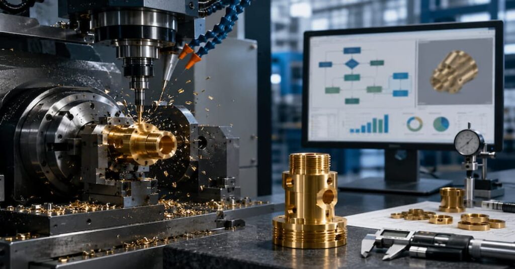
In precision manufacturing, the difference between a component that performs flawlessly and one that fails under load often comes down to what was anticipated before machining began. Process Failure Mode and Effects Analysis, or PFMEA, helps manufacturers identify risks before they become costly failures. For brass, a material with unique machining behaviour, generic FMEA templates are often not enough.
For manufacturers working with architectural brass components, material-specific risks such as galling, burr formation, work hardening, and dimensional drift can affect quality, delivery timelines, and customer satisfaction. This guide explains how to apply brass-specific PFMEA in CNC operations for both production facilities and specialized job shops.
What Are the Fundamentals of PFMEA?
The AIAG/VDA 7-Step Approach Explains the Methodology
The AIAG/VDA FMEA Handbook is the current industry standard for process failure analysis. It replaces the older approach with a more structured seven-step method that helps teams identify, evaluate, and reduce risks before they become actual defects.
The Seven PFMEA Steps Guide Risk Identification and Control
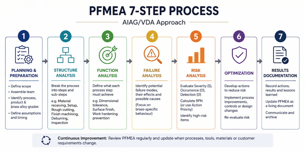
The seven steps of PFMEA are:
- Planning and Preparation: Define the scope, team, timing, and brass alloy grades involved, such as C36000, C46400, and C93200.
- Structure Analysis: Break the process into steps such as material receiving, setup, rough cutting, finish machining, deburring, and inspection.
- Function Analysis: Define what each process step must achieve, such as Ra 0.8 to 1.6 μm surface finish, ±0.05mm tolerance, or prevention of work hardening.
- Failure Analysis: Identify possible failure modes, effects, and causes. This is where brass-specific knowledge is important.
- Risk Analysis: Evaluate Severity, Occurrence, and Detection to calculate RPN, even though the newer AIAG/VDA method also uses Action Priority.
- Optimization: Develop actions to reduce risk through process changes, controls, or design improvements.
- Results Documentation: Record lessons learned and update the PFMEA as a living document.
Standard PFMEA Templates May Not Work Well for Brass
Generic PFMEA templates usually cover common issues such as dimensional variation, surface defects, and tool wear. However, brass, a copper-zinc alloy, has unique properties that require closer attention.
Brass-specific concerns include:
- Galling tendency: Brass’s softness and low melting point create adhesion risks with cutting tools.
- Burr formation: Its ductility can cause burrs that are difficult to remove cleanly.
- Work hardening: Cold working can increase hardness by 20% to 30%, affecting later operations.
- Thermal conductivity: Rapid heat dissipation affects cutting temperatures, tool life, and dimensional stability.
How Do Brass Material Properties Affect Failure Modes?
Different Brass Alloys Create Different CNC Risks
Not all brass alloys behave the same. Composition affects machinability, failure probability, and PFMEA severity ratings.
| Alloy | Composition | Machinability Rating | Key Characteristics | Primary Failure Risks |
| C36000 Free-Cutting Brass | 61.5% Cu, 35.5% Zn, 3% Pb | 100% baseline | Excellent machinability, lead content for chip breaking | Lead distribution, surface lead smearing |
| C46400 Naval Brass | 60% Cu, 39.25% Zn, 0.75% Sn | 30% | High corrosion resistance, added tin | Work hardening, galling |
| C93200 Bearing Bronze | 83% Cu, 7% Sn, 7% Pb, 3% Zn | 50% | High lead content, bearing applications | Porosity, lead segregation |
| C38500 Architectural Bronze | 57% Cu, 40% Zn, 3% Pb | 90% | Good for extrusions and trim | Extrusion seam defects, anisotropic properties |
Material Properties Should Be Linked to Specific Failure Modes
When creating a brass PFMEA, material properties should be connected directly to likely failure modes.
Thermal Conductivity, 109 to 125 W/m·K
- Failure Mode: Cutting edge temperature fluctuation.
- Effect: Thermal cracking of inserts and dimensional instability.
- Occurrence Rating: 6, moderate to high for high-speed operations.
Ductility, 40% to 55% elongation
- Failure Mode: Excessive deformation during cutting.
- Effect: Burr formation, poor finish, and dimensional creep.
- Occurrence Rating: 7, high for finishing operations.
Low Melting Point, 900°C to 940°C
- Failure Mode: Built-up edge formation.
- Effect: Surface tearing, increased cutting forces, and tool wear.
- Occurrence Rating: 5, depending on cutting speed.
Tendency to Work Harden
- Failure Mode: Surface hardness increase during machining.
- Effect: Lower machinability, higher tool wear, and possible cracking.
- Occurrence Rating: 6, moderate to high for interrupted cuts.
How Should PFMEA Be Applied Across CNC Operation Phases?
Setup and Qualification Establish the Foundation for Quality
The setup phase controls the starting accuracy of the process. In brass machining, thermal expansion and workpiece stability are especially important.
Key process elements include:
- Workpiece fixturing and clamping force
- Tool presetting and offset verification
- Machine warm-up and thermal stabilization
- First-piece qualification
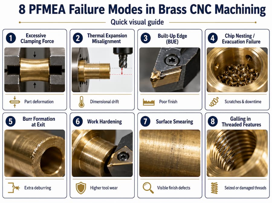
Failure Mode 1: Excessive Clamping Force
- Effect: Workpiece deformation and dimensional non-conformance.
- Severity: 8, due to customer dissatisfaction and assembly issues.
- Cause: Brass has lower yield strength of 124 to 310 MPa compared to steel.
- Current Controls: Torque-limited clamping fixtures and soft jaws.
- RPN: 8 × 6 × 4 = 192, High Priority.
- Recommendation: Use fixture pressure monitoring and specify maximum clamping force in setup sheets.
Failure Mode 2: Thermal Expansion Misalignment
- Effect: Z-axis drift and incorrect depth of cut.
- Severity: 7, due to dimensional variation.
- Cause: Brass thermal expansion coefficient of 20.5 × 10⁻⁶/°C affects positioning.
- Current Controls: Machine warm-up and ambient temperature monitoring.
- RPN: 7 × 5 × 5 = 175, High Priority.
Rough Cutting Requires Heat and Chip Control
Rough machining removes bulk material and establishes basic geometry. For brass, heat generation and chip evacuation are major concerns.
Failure Mode 3: Built-Up Edge Formation
- Effect: Poor surface finish, increased cutting forces, and dimensional variation.
- Severity: 7.
- Cause: Brass adhesion to the tool due to low melting point and high ductility.
- Occurrence: 6, common at moderate cutting speeds.
- Detection: 4, through visual inspection and surface finish measurement.
- RPN: 168.
- Mitigation: Use polished tool coatings such as TiAlN or DLC, cutting speeds of 300 to 600 SFM, and high-pressure coolant.
Failure Mode 4: Chip Nesting and Evacuation Failure
- Effect: Surface scratching, tool damage, and machine downtime.
- Severity: 6.
- Cause: Long, stringy chips from high-ductility brass alloys.
- Occurrence: 5.
- Detection: 3, through machine alarms and visual monitoring.
- RPN: 90.
- Mitigation: Use chip breakers, through-spindle coolant, and programmed chip breaks.
Finish Machining Determines Final Part Quality
Finish operations determine the final dimensions, surface finish, and visible quality of the part.
Failure Mode 5: Burr Formation at Exit
- Effect: Extra deburring, surface damage, and longer cycle time.
- Severity: 6.
- Cause: Brass ductility causes material tearing instead of clean shearing.
- Occurrence: 8, very high for through-features.
- Detection: 4, through visual inspection and touch probe verification.
- RPN: 192.
- Mitigation: Use exit chamfers, sharp cutting edges below 0.01mm hone radius, reduced feed at exit, and back chamfer tools.
Failure Mode 6: Work Hardening During Finishing
- Effect: Higher tool wear in later operations and surface hardness variation.
- Severity: 5.
- Cause: Cold working from previous operations or aggressive cutting parameters.
- Occurrence: 6.
- Detection: 5, through microhardness testing and surface analysis.
- RPN: 150.
- Mitigation: Use intermediate annealing for complex parts, optimized tool paths, and sharp cutting tools.
Deburring and Finishing Protect the Final Appearance
Post-machining operations are especially important for architectural brass components where appearance matters.
Failure Mode 7: Surface Smearing During Deburring
- Effect: Visible defects, uneven patina absorption, and rejected parts.
- Severity: 8, due to aesthetic failure.
- Cause: Brass softness allows abrasive media to embed or smear.
- Occurrence: 6.
- Detection: 3, through visual inspection under magnification.
- RPN: 144.
- Mitigation: Use ceramic media, controlled processing time, and dedicated brass-only finishing equipment.
Failure Mode 8: Galling in Threaded Features
- Effect: Seized fasteners, stripped threads, and field failures.
- Severity: 9, due to potential complete part replacement.
- Cause: Adhesion between brass threads under load, especially with similar brass fasteners.
- Occurrence: 5.
- Detection: 6, through torque testing and thread gauge inspection.
- RPN: 270, Critical Priority.
- Mitigation: Specify anti-seize compound, optimize thread tolerance, and recommend dissimilar fastener materials.
What Failure Modes Should Be Included in a Brass CNC PFMEA?
Cutting Tool-Related Failures Can Affect Accuracy and Surface Finish
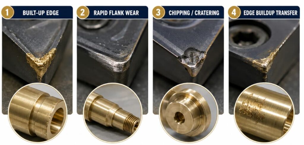
| Failure Mode | Potential Effect | S | Cause | O | Control | D | RPN | Recommended Action |
| Built-up edge | Poor finish, dimensional drift | 7 | Low speed, uncoated tools | 6 | Tool life monitoring | 4 | 168 | Set minimum SFM and use polished tool coatings |
| Rapid flank wear | Loss of accuracy | 8 | Abrasive constituents, heat | 5 | Scheduled tool changes | 5 | 200 | Optimize parameters and tool wear compensation |
| Chipping/cratering | Sudden tool failure | 9 | Intermittent cutting, vibration | 4 | Tool monitoring | 3 | 108 | Smooth entry/exit and reduce radial engagement |
| Edge buildup transfer | Surface contamination | 6 | BUE break-off | 5 | In-process inspection | 4 | 120 | Improve coolant and chip evacuation |
Workpiece-Related Failures Can Cause Burrs, Drift, and Cracking
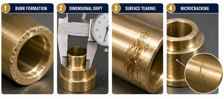
| Failure Mode | Potential Effect | S | Cause | O | Control | D | RPN | Recommended Action |
| Burr formation | Extra processing, surface damage | 6 | Ductile material behaviour | 8 | Visual inspection | 4 | 192 | Optimize exit strategy and use back chamfering |
| Dimensional drift | Assembly interference | 8 | Thermal expansion, work hardening | 5 | In-process probing | 4 | 160 | Use thermal compensation and intermediate checks |
| Surface tearing | Aesthetic rejection | 8 | BUE, dull tools | 5 | Surface finish check | 3 | 120 | Improve tool condition and parameters |
| Microcracking | Weakness, corrosion initiation | 9 | Excessive work hardening | 4 | Dye penetrant inspection | 6 | 216 | Use stress relief and review parameters |
Process-Related Failures Can Lead to Rework or Rejection
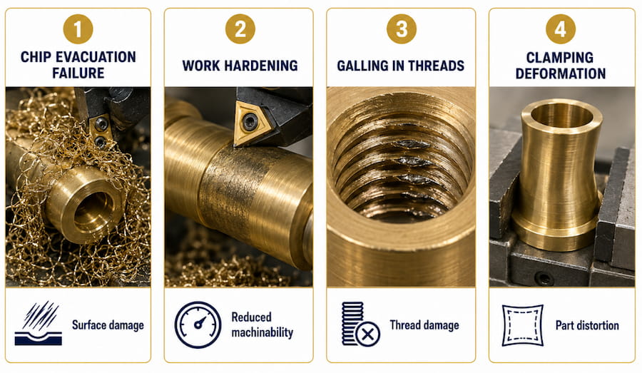
| Failure Mode | Potential Effect | S | Cause | O | Control | D | RPN | Recommended Action |
| Chip evacuation failure | Surface damage, tool breakage | 7 | Stringy chips, poor coolant | 6 | Machine alarms | 3 | 126 | Use high-pressure coolant and maintain conveyors |
| Work hardening | Reduced machinability | 6 | Excessive cold working | 6 | Hardness testing | 5 | 180 | Optimize depth of cut and consider annealing |
| Galling in threads | Seizure, fastener failure | 9 | Material adhesion | 5 | Torque testing | 6 | 270 | Use anti-seize and review thread design |
| Clamping deformation | Dimensional non-conformance | 8 | Excessive force | 6 | Setup verification | 4 | 192 | Use torque-limited fixtures and soft jaws |
How Does a Brass Architectural Component PFMEA Work in Practice?
A Custom Brass Door Hardware Component Shows Common PFMEA Risks
Part Description: Solid brass lever handle made from C36000, requiring precision machining of mounting features, threaded insert bores, and mirror-finish visible surfaces.
Manufacturing Process Flow:
- Bar stock receiving and inspection
- CNC turning, rough and finish
- CNC milling, mounting features
- Thread milling, M8 mounting threads
- Deburring and surface finishing
- Protective lacquer application
- Final inspection and packaging
The PFMEA Excerpt Highlights Finish Turning Issues
Process Step: CNC Turning, Finish Profile
Function: Generate final handle profile to ±0.1mm tolerance with Ra 0.4 μm surface finish on visible surfaces.
| Failure Mode | Potential Effect | S | Cause | O | Prevention | Detection | D | RPN | Action Recommended |
| Visible burr at shoulder | Customer rejection | 8 | Ductile tearing at exit | 7 | Lead-out, sharp tools | 100% visual inspection | 3 | 168 | Add back-turning and reduce feed 50% at exit |
| Diameter variation | Assembly interference | 8 | Thermal expansion, tool wear | 5 | Tool tracking, constant SFM | In-process probing | 4 | 160 | Add mid-batch probe check and wear compensation |
| Surface finish non-conformance | Aesthetic rejection | 7 | BUE, improper feed/speed | 6 | Parameter cards, coated inserts | Roughness check | 4 | 168 | Use TiAlN inserts and optimize feed |
| Work hardening in bore | Thread milling difficulty | 6 | Aggressive roughing | 6 | Roughing limits | Hardness spot check | 5 | 180 | Reduce roughing depth and add stress relief |
Recommended Actions Can Reduce RPN and Improve Yield
After implementing the recommended actions, RPN values were reduced:
- Visible burr: 168 to 72, a 57% reduction
- Dimensional variation: 160 to 96, a 40% reduction
- Surface finish: 168 to 84, a 50% reduction
- Work hardening: 180 to 90, a 50% reduction
First-pass yield improved from 87% to 96%, and surface-quality complaints dropped to zero over six months.
How Can SPC Be Integrated with PFMEA and Control Plans?
PFMEA Should Be Linked to Statistical Process Control
A PFMEA without Statistical Process Control, or SPC, is only a theoretical exercise. The value comes when risk prevention becomes real-time monitoring.
Control Plans Should Be Developed from High-Risk Failure Modes
For each high-RPN failure mode, the control plan should define the control method, measurement technique, sample frequency, control limits, and reaction plan.
SPC Chart Selection Should Match the Failure Mode
| Failure Mode | SPC Chart Type | Rationale | Key Variables |
| Dimensional drift | X-bar and R Chart | Monitors average and variation | Diameter, length |
| Surface finish | Individual-X and Moving Range | Suitable for low-volume checks | Ra values |
| Tool wear trend | CUSUM or EWMA | Detects small changes early | Tool compensation values |
| Burr occurrence | p-chart or np-chart | Tracks pass/fail results | Burr presence |
| Work hardening | Individual-X | Suitable for batch checks | Microhardness readings |
Digital Integration Can Connect PFMEA to MES Systems
Modern Manufacturing Execution Systems, or MES, can connect PFMEA data to production workflows. This supports automated inspection triggers, real-time alerts, closed-loop feedback, and traceability across material lots, process parameters, and inspection results.
How Should Job Shops and Production Facilities Adapt PFMEA?
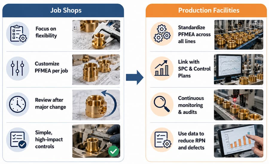
Job Shops Face Small-Batch PFMEA Challenges
Job shops often face lower production volumes, higher part variety, limited quality engineering resources, and changing customer requirements.
Generic Process PFMEA Templates Help Reduce Repeated Work
Job shops can create master PFMEAs for process families instead of starting from zero each time. Examples include:
- Brass Turning Operations, C36000
- Brass Milling Operations, All Alloys
- Brass Thread Generation
These templates can then be adapted for each new part.
Risk-Based Sampling Helps Prioritize Important Features
Not all features need the same level of scrutiny.
Class A, Critical: Safety-related features, customer-specified critical features, and tolerances below ±0.05mm.
Approach: Full PFMEA with all recommended actions.
Class B, Major: Functional but not safety-critical features, with tolerances of ±0.05mm to ±0.2mm.
Approach: Standard PFMEA with actions for RPN values above 150.
Class C, Minor: Aesthetic or non-critical features, with tolerances above ±0.2mm.
Approach: Abbreviated PFMEA focused on the highest-risk issues.
Pre-Validated Process Windows Support Faster Decision-Making
| Operation | Cutting Speed, SFM | Feed Rate, mm/rev | Depth of Cut, mm | Validated For |
| Rough Turning | 400 to 600 | 0.15 to 0.25 | 2.0 to 5.0 | C36000, C38500 |
| Finish Turning | 500 to 800 | 0.05 to 0.15 | 0.25 to 1.0 | C36000, C38500 |
| Rough Milling | 300 to 500 | 0.10 to 0.20 | 3.0 to 6.0 | All brass grades |
| Finish Milling | 400 to 700 | 0.05 to 0.10 | 0.2 to 0.5 | All brass grades |
When parameters stay within proven windows, some failure modes can receive lower occurrence ratings.
ASEAN Manufacturers Should Consider Supplier, Climate, and Workforce Factors
For ASEAN manufacturing, PFMEA should also consider supplier quality variation, mill test reports, incoming material testing, high humidity, temperature variation, power quality, workforce training, language barriers, and escalation procedures.
How Should RPN and Action Priority Be Used for Brass CNC Operations?
RPN Helps Evaluate and Rank Process Risk
Although the AIAG/VDA method now uses Action Priority, RPN is still widely used.
RPN Formula: RPN = Severity × Occurrence × Detection
| Rating | Severity | Occurrence | Detection |
| 1 | No effect | ≤ 1 in 1,500,000 | Almost certain |
| 2 to 3 | Minor annoyance | 1 in 150,000 to 1 in 15,000 | High probability |
| 4 to 6 | Moderate effect | 1 in 2,000 to 1 in 100 | Moderate probability |
| 7 to 8 | High impact | 1 in 50 to 1 in 10 | Low probability |
| 9 to 10 | Safety or critical | ≥ 1 in 5 | Very low or none |
RPN Thresholds Help Prioritize Corrective Actions
| RPN Range | Priority | Action Required |
| 1 to 80 | Low | Monitor |
| 81 to 150 | Moderate | Action recommended |
| 151 to 250 | High | Action required |
| 251 to 400 | Critical | Immediate action and escalation |
| 401 to 1000 | Emergency | Stop production until mitigated |
Brass Requires Special Attention for Severity and Detection
Safety-related failures with Severity 9 to 10 should always be addressed. Galling in structural threads should be treated as critical, and stress corrosion cracking should receive elevated severity for outdoor applications.
Detection can also be difficult. Microcracks may require dye penetrant inspection, subsurface work hardening may require destructive testing, and surface smearing can hide defects.
Why Is Brass-Specific PFMEA Important for CNC Operations?
PFMEA is not just a checklist. It is a living method for turning reactive quality management into proactive risk control. For brass CNC operations, a material-specific PFMEA can help reduce rework, improve first-pass yield, and prevent quality escapes.
The framework in this guide gives teams a practical starting point. However, the real value comes from applying it to specific machines, parts, processes, and customer requirements. PFMEAs should be updated as processes change, and each failure should be treated as a chance to improve future risk assessment.
For job shops, a strong PFMEA supports better quoting, fewer rejected parts, and higher customer confidence. For production facilities, linking PFMEA with SPC creates a closed-loop quality system where data supports continuous improvement.
Reference Tables
Brass Grade Selection Helps Match Applications to PFMEA Focus Areas
| Application | Recommended Grade | Key PFMEA Focus |
| Interior hardware | C36000 | Lead distribution, surface smearing |
| Exterior or marine hardware | C46400 | Work hardening, galling prevention |
| Bearing surfaces | C93200 | Porosity, lead segregation |
| Architectural extrusions | C38500 | Anisotropic properties, seam defects |
Cutting Parameter Tables Support Process Planning
| Operation | SFM Range | Feed, mm/rev | Depth, mm | Coolant |
| Rough Turn | 400 to 600 | 0.15 to 0.25 | 2.0 to 5.0 | Flood soluble |
| Finish Turn | 500 to 800 | 0.05 to 0.15 | 0.25 to 1.0 | High-pressure |
| Rough Mill | 300 to 500 | 0.10 to 0.20 per tooth | 3.0 to 6.0 | Through-spindle |
| Finish Mill | 400 to 700 | 0.05 to 0.10 per tooth | 0.2 to 0.5 | Mist or minimal |
Common Failure Mode Tables Help Teams Diagnose Issues Quickly
| Failure Mode | Most Common Causes | Quick Check |
| Burr formation | Dull tools, fast exit feed, high ductility | Tool condition and exit strategy |
| Galling | Similar materials, no lubrication, high load | Fastener material and anti-seize use |
| Work hardening | Large depths of cut, slow speeds, dull tools | Cutting parameters and tool sharpness |
| Built-up edge | Moderate speeds, uncoated tools, high ductility | Cutting speed and tool coating |
| Dimensional drift | Thermal effects, tool wear, machine warm-up | Thermal compensation and tool life tracking |
Conclusion
Brass-specific PFMEA is essential for CNC operations because brass does not behave the same way as steel, aluminium, or other common engineering materials. Its ductility, low melting point, galling tendency, burr formation risk, and work hardening behaviour can all affect machining quality if they are not properly controlled. By identifying these risks early, manufacturers can reduce rework, improve first-pass yield, protect surface quality, and maintain tighter control over production outcomes.
A strong PFMEA should not be treated as a one-time checklist. It should be updated as tools, machines, materials, suppliers, and customer requirements change. When PFMEA is connected with SPC, control plans, inspection routines, and real-time production feedback, it becomes a practical system for preventing failures before they affect delivery timelines or customer satisfaction.
At Align Manufacturing, we understand that successful brass CNC production depends on more than machining capability alone. From our perspective, reliable sourcing, clear communication, supplier control, quality inspection, and process discipline are just as important as cutting parameters. As companies look for dependable Vietnam precision machining solutions, we help connect projects with trusted manufacturing partners across Vietnam and the wider region, supporting customers from engineering review to production, inspection, and logistics.
Brass Surface Finishes: From Polish to Powder Coat for Function & Aesthetics
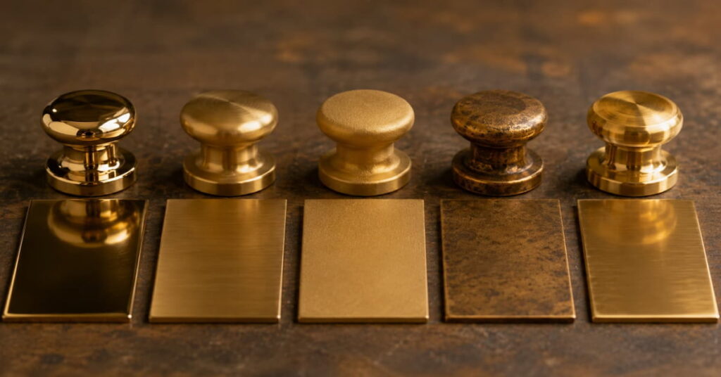
Why Does Brass Finishing Matter?
Brass Finishing Improves Appearance, Protection, and Performance
Brass is valued for its warm golden colour, good machinability, corrosion resistance, and versatility. It is used in architectural hardware, marine components, musical instruments, plumbing fixtures, decorative parts, consumer products, and precision components. However, raw brass is only the starting point. Without the right surface finish, brass can tarnish, show machining marks, lose visual appeal, or fail to meet the performance needs of demanding applications.
Surface finishing transforms brass from a basic machined material into a finished component with improved durability, appearance, corrosion resistance, wear performance, and cleanability. The right finish can preserve the natural brass look, create a modern satin texture, add a protective coating, or completely change the surface for industrial use.
Common reasons for finishing brass include:
- Improving visual appeal
- Reducing tarnishing
- Increasing corrosion resistance
- Improving wear resistance
- Creating a specific texture or colour
- Making the surface easier to clean
- Preparing the part for outdoor, marine, medical, or decorative use
Choosing the correct finish depends on how the brass part will be used. A decorative indoor handle may only need polishing and lacquer, while outdoor architectural hardware may need powder coating or PVD coating. A marine component may need saltwater protection, while a medical or food service component may need a cleanable, non-toxic surface.
Why Is Brass Composition Important Before Finishing?
Brass Grade Affects Finish Quality and Durability
Brass is mainly made from copper and zinc. The ratio of these metals affects the material’s colour, strength, machinability, corrosion resistance, and finishing behaviour. Different brass grades respond differently to polishing, plating, coating, and chemical treatment.
- C260 Cartridge Brass: Contains around 70% copper and 30% zinc. It is suitable for polishing and plating and offers good corrosion resistance.
- C360 Free-Cutting Brass: Known for excellent machinability, but it may contain lead, which can affect plating and regulatory requirements.
- C464 Naval Brass: Contains added tin for better corrosion resistance, making it suitable for marine applications.
- C485 Leaded Brass: Offers improved machinability, but some environmental regulations may limit its finishing options.
Understanding the brass grade matters because finishing is not only about appearance. The metal composition can affect coating adhesion, colour consistency, corrosion performance, and compatibility with different finishing processes.
As-Machined Brass Is Usually the Starting Surface
As-machined brass often has tool marks, small imperfections, and a raw metallic appearance. In some industrial applications, this may be acceptable. However, most decorative, architectural, and consumer-facing brass parts require additional finishing to improve appearance and performance.
The as-machined surface typically has a roughness of around 32-125 microinches Ra, depending on machining conditions. From this starting point, the surface can be polished, brushed, bead blasted, lacquered, plated, powder coated, patinated, or treated with advanced coatings.
What Mechanical Finishes Are Used for Brass?
Polished Brass Creates a Classic Mirror Finish
Polished brass is one of the most recognisable brass finishes. It creates a bright, reflective, mirror-like surface that highlights the natural golden colour of the material. This finish is common in luxury hardware, decorative parts, musical instruments, architectural details, and premium fixtures.
The polishing process uses progressive abrasion. It usually starts with coarser compounds, such as 80-120 grit, before moving to finer polishing compounds that can reach up to 10,000 grit. Modern facilities may use automated buffing wheels, robotic polishing arms, and polishing compounds designed specifically for brass.
Key features of polished brass include:
- Bright mirror-like appearance
- High reflectivity, usually around 85-95% gloss
- Surface roughness of around 2-8 microinches Ra
- Premium decorative appeal
- Improved cleanability
- Higher maintenance compared to matte finishes
Functionally, polishing can improve cleanability, reduce friction, minimise bacterial adhesion, and support optical or decorative applications. However, polished brass requires regular maintenance because exposed brass can tarnish over time. Mild soap, soft cloths, brass wax, clear lacquer, and reduced exposure to humidity or salt air can help preserve the finish.
Brushed Brass Creates a Satin Directional Finish
Brushed brass, also called satin brass, creates a softer and more modern appearance than mirror-polished brass. Instead of being highly reflective, it has fine directional lines across the surface. This gives the brass a contemporary look while helping to hide fingerprints, small scratches, and everyday wear.
The brushing process uses abrasive belts, wheels, or hand tools to create uniform directional scratches. A fine satin finish may use 180-240 grit abrasives, while a coarser brushed finish may use 80-120 grit materials. The final surface roughness is usually around 16-64 microinches Ra.
Brushed brass is often chosen because it:
- Creates a modern satin look
- Reduces glare
- Hides fingerprints better than polished brass
- Conceals minor scratches more effectively
- Offers better grip
- Requires less maintenance than mirror-polished brass
Brushed brass is popular in kitchen fixtures, consumer electronics, automotive interiors, commercial hardware, and modern architectural details. However, brushed finishes can show wear patterns over time, especially in high-contact areas. For the best appearance, the brushing direction should remain consistent across the full part.
Bead Blasting Creates a Uniform Matte Texture

Bead blasting uses small glass, ceramic, or stainless steel beads propelled at high velocity against the brass surface. This creates a uniform matte texture without directional grain. Unlike brushed brass, bead blasted brass has a more even, non-directional appearance.
Typical media size ranges from 50-200 microns, while pressure may range from 40-100 psi depending on the desired texture. The resulting surface roughness is usually around 32-125 microinches Ra.
Bead blasted brass is useful when the goal is to create:
- A non-directional matte surface
- Reduced glare
- Better coating adhesion
- A consistent finish on complex shapes
- Better concealment of manufacturing imperfections
Bead blasted brass is often used for scientific instruments, industrial controls, marine hardware, architectural parts, and components that need reduced glare. Another major benefit is coating adhesion. Because bead blasting creates a lightly textured surface, it is often used before painting, powder coating, or other protective coatings.
What Chemical and Electrochemical Finishes Are Available for Brass?
Clear Lacquering Preserves the Natural Brass Appearance
Clear lacquering involves applying a transparent protective coating over brass. The coating is usually acrylic, polyurethane, or epoxy-based. Its purpose is to slow tarnishing while allowing the natural brass colour to remain visible.
Common application methods include:
- Spray coating for thin, uniform films
- Dip coating for complex parts that need full coverage
- Electrostatic spray for efficient application and reduced overspray
Typical film thickness ranges from 0.5-2.0 mils, or 12-50 microns. Depending on the formulation, the coating may air dry, thermally cure, or UV cure. With proper surface preparation, clear lacquer can achieve strong adhesion ratings.
Clear lacquer maintains most of the underlying brass appearance and can be produced in gloss, semi-gloss, or matte finishes. Its main limitation is durability. Outdoors, quality clear lacquer may last around 2-5 years before showing yellowing, cracking, peeling, or wear. Indoors, it may last around 5-10 years with proper care. For longer-lasting protection, clear powder coating or PVD coating may be better.
Electroplating Adds a Durable Metallic Surface
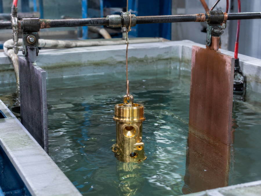
Electroplating deposits a thin metal layer onto brass through an electrochemical process. Nickel plating is one of the most common choices because it provides a bright, durable, corrosion-resistant surface. It can also act as an undercoat for chromium plating.
Nickel plating is valued because it provides:
- A bright or satin metallic appearance
- Good corrosion resistance
- Good wear resistance
- Increased surface hardness
- Better durability for plumbing, marine, and automotive parts
- Metallic conductivity compared to powder coating
A typical nickel plating bath may contain nickel sulfate, nickel chloride, and boric acid. Current density may range from 20-50 amps per square foot, while deposition rates may range from 0.0005″-0.002″ per hour. Decorative nickel plating thickness is usually around 0.0002″-0.001″.
Compared to powder coating, nickel plating keeps a metallic finish and maintains conductivity. Powder coating usually provides stronger outdoor protection, better UV resistance, and more colour flexibility, but it is thicker and electrically insulating. The better option depends on whether the part needs appearance, conductivity, wear resistance, or environmental protection.
Chemical Patinas Create Controlled Aging Effects
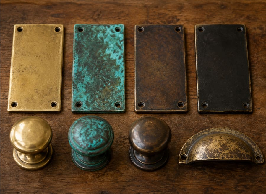
Chemical patinas use controlled reactions to create aged, darkened, or artistic brass finishes. They are often used in restoration work, decorative arts, architectural details, custom hardware, and artistic installations.
Common patina types include:
- Verdigris: Creates blue-green aged effects
- Antique brown: Creates brown-black tones
- Heat patina: Creates iridescent oxide colours
- Selective patina: Creates decorative contrast on specific areas
Patina results depend on surface preparation, chemical concentration, temperature, exposure time, and application method. Because patinas can wear unevenly in high-contact areas, they are usually sealed with lacquer, wax, polyurethane, epoxy clear coat, or clear powder coating. This helps preserve the aged appearance while improving durability.
What Advanced Coating Technologies Are Used for Brass?
Powder Coating Provides Durable Protection and Colour Flexibility
Powder coating uses dry powder particles that are electrostatically applied to grounded brass parts. The coated part is then heated so the powder melts, flows, and cures into a continuous protective film.
Powder coating is one of the strongest options for outdoor brass. Super durable polyester formulations offer good UV resistance, corrosion protection, mechanical durability, and design flexibility. In harsher environments, a two-coat system may be used, such as an epoxy primer for corrosion resistance and a polyester topcoat for UV stability.
Good surface preparation is essential before powder coating. The usual steps include:
- Degreasing to remove oils and contaminants
- Mechanical profiling using glass beads or aluminium oxide
- Chemical pretreatment using zirconium or silane coatings
- Outgassing for cast brass parts
- Controlled curing at the correct part metal temperature
Brass presents some technical challenges during powder coating. Its high electrical conductivity can create Faraday cage effects in corners or recessed areas. Its high thermal conductivity means it heats faster than steel, so cure profiles may need adjustment. Zinc migration can also affect adhesion if pretreatment is poor.
Powder formulations for brass include TGIC polyester, epoxy-polyester hybrids, clear powders, and metallic powders. Clear powder coatings can protect brass while maintaining its natural golden colour, but the surface must be prepared carefully because imperfections may remain visible beneath the clear coating.
PVD Coating Provides High-Tech Wear Resistance
PVD, or Physical Vapor Deposition, creates ultra-thin, hard coatings in a vacuum environment. These coatings improve hardness, wear resistance, friction performance, and appearance while adding very little thickness.
Common PVD coatings for brass include:
- Titanium Nitride (TiN): Gold-coloured and extremely hard
- Chromium Nitride (CrN): Silver-gray with good corrosion resistance
- Diamond-Like Carbon (DLC): Black, low-friction, and highly wear-resistant
PVD coating thickness is usually around 1-5 microns. Process temperatures may range from 400-900°F, or 204-482°C. These coatings can reach very high hardness levels, such as 2000-3000 HV.
Compared to traditional plating, PVD is thinner, harder, and more wear-resistant. Traditional electroplating can provide good corrosion resistance and may cover internal surfaces more effectively, but PVD is better for precision components where dimensional accuracy, low friction, and hardness matter.
What Functional Finishes Are Used for Specialized Brass Applications?
Specialized Finishes Can Add Antimicrobial, Low-Friction, or Thermal Properties
Some brass parts require more than appearance and corrosion protection. Functional finishes can improve hygiene, reduce friction, or control heat transfer.
Specialized brass finishes may include:
- Antimicrobial finishes for high-touch healthcare or food service surfaces
- PTFE-based low-friction coatings for sliding or moving parts
- Thermal control finishes for electronics, aerospace, and energy systems
- Food-safe coatings for cleanable, non-toxic surfaces
For healthcare and food service, antimicrobial finishes can enhance brass’s natural copper-based antimicrobial properties. Surface treatments such as micro-roughening, porous coatings, or ion-exchange treatments can increase copper ion availability.
For mechanical applications, low-friction coatings may be used. PTFE, commonly known as Teflon, can be embedded in nickel or other coating matrices to create self-lubricating surfaces. These coatings are useful for bearings, seals, sliding parts, fasteners, and molds.
For food service applications, brass finishes must be non-toxic, cleanable, and corrosion-resistant. Suitable options may include FDA-compliant powder coatings, food-safe nickel plating, certified clear lacquers, and approved PVD coatings.
How Do You Choose the Right Brass Finish?
Match the Finish to Environment, Function, Appearance, and Cost
The right brass finish depends on the environment, performance needs, appearance goals, budget, and regulatory requirements.
Before selecting a finish, consider:
- Environment: Indoor, outdoor, marine, chemical, or high-humidity exposure
- Function: Corrosion resistance, wear resistance, low friction, conductivity, or cleanability
- Appearance: Bright, brushed, matte, aged, coloured, or metallic
- Maintenance: How often the surface can be cleaned, polished, or refinished
- Cost: Initial finishing cost versus long-term maintenance
- Compliance: RoHS, REACH, FDA, NSF, or industry-specific requirements
For example, powder coating is strong for outdoor durability, nickel plating is useful for metallic appearance and wear resistance, and PVD works well for precision wear applications. Polished brass creates a bright luxury look, brushed brass creates a modern satin finish, bead blasting creates a matte industrial texture, and patinas create aged or artistic effects.
How Do Brass Finishes Compare?
Each Finish Offers a Different Balance of Durability, Maintenance, and Cost
| Finish Type | Cost Index | Durability | Maintenance | Aesthetic Range | Best Applications |
| Polished | 1.0 | Medium | High | Natural brass | Decorative, optical, luxury |
| Brushed | 1.2 | Medium-High | Medium | Moderate | Commercial, consumer, automotive |
| Clear Lacquer | 1.5 | Medium | Low | Natural brass | Indoor decorative, collectibles |
| Nickel Plate | 2.0 | High | Low | Metallic silvers | Plumbing, marine, automotive |
| Powder Coat | 2.5 | Very High | Very Low | Unlimited colours | Architectural, outdoor, industrial |
| PVD Coating | 5.0+ | Extreme | Very Low | Metallic colours | Precision, wear, medical |
| Chemical Patina | 3.0 | Low-Medium | Medium | Artistic effects | Restoration, decorative arts |
A finish with a lower upfront cost may not always be the most economical choice. Total cost of ownership includes the initial cost, annual maintenance, expected service life, and possible replacement cost.
For example, polished brass with lacquer may cost less at first but require more maintenance. Powder coated brass may cost more initially but last longer with less maintenance. PVD coating may have the highest initial cost, but its durability may justify the expense for critical or high-wear applications.
What Quality Tests Are Used for Brass Finishing?
Testing Confirms Adhesion, Corrosion Resistance, and Surface Durability
Quality control ensures that the finish performs as expected. The most common tests check adhesion, corrosion resistance, wear resistance, and outdoor durability.
Important brass finishing tests include:
- Cross-hatch testing to check coating adhesion
- Pull-off testing to measure bond strength
- Salt spray testing to assess corrosion resistance
- Humidity testing to evaluate blistering or adhesion loss
- Abrasion testing to measure wear resistance
- Pencil hardness testing to check scratch resistance
- Weathering tests to simulate UV exposure and outdoor aging
These tests help confirm whether the finish can survive handling, cleaning, environmental exposure, and long-term use.
Which Brass Finishes Work Best by Industry?
Different Applications Require Different Surface Priorities
Different industries require different brass surface priorities. A decorative product may need visual appeal, while an outdoor component may need corrosion resistance. A food service part must be cleanable and safe, while a precision component may need hardness and low friction.
Common industry choices include:
- Architectural hardware: Powder coating, PVD coating, nickel plating, brushed brass, or lacquered brass
- Marine applications: Powder coating with epoxy primer, electroplated nickel, antifouling coatings, or copper-nickel alloys
- Medical devices: PVD coatings, epoxy powder coatings, antimicrobial copper finishes, or cleanable certified coatings
- Food service equipment: FDA-compliant powder coatings, food-safe nickel plating, certified clear lacquers, or approved PVD coatings
- Consumer electronics: Brushed brass, PVD coatings, textured powder coating, or fingerprint-resistant finishes
Each industry should select a finish based on exposure, cleaning methods, handling frequency, safety requirements, and expected service life.
What Is the Environmental Impact of Brass Finishing?
Environmental Impact Depends on Chemicals, Energy, Wastewater, and Dust
Different brass finishing processes have different environmental impacts. Electroplating can generate hazardous wastewater and may use toxic chemicals, so proper treatment and disposal are required. Powder coating is VOC-free and allows overspray recovery, but it requires energy for curing. PVD produces minimal waste and avoids many hazardous chemicals, but it uses significant energy. Mechanical finishing uses fewer chemicals but creates dust that must be collected.
Modern finishing facilities reduce environmental impact through:
- Closed-loop water systems
- Powder overspray recovery
- Improved filtration
- Safer pretreatment chemistry
- Energy-efficient curing ovens
- Dust collection systems for mechanical finishing
Sustainable finishing is becoming more important as manufacturers look for lower-waste and lower-emission processes.
What Future Trends Are Shaping Brass Finishing?
Brass Finishing Is Moving Toward Sustainability and Smarter Coatings

Brass finishing is moving toward cleaner, smarter, and more controlled processes. Sustainable coatings aim to reduce VOCs, wastewater, and chemical hazards. Water-based coatings and bio-based polymers are becoming more important as manufacturers look for environmentally responsible options.
Smart and advanced developments include:
- Self-healing coatings that release repair agents when scratched
- Thermochromic coatings that change colour with temperature
- Photochromic finishes that respond to light exposure
- Anti-fingerprint nanocoatings for high-touch products
- Digital colour matching for better consistency
- Machine vision inspection for automated quality control
- IoT equipment monitoring for predictive maintenance
These technologies help improve durability, reduce waste, and make finishing quality more consistent across production runs.
Conclusion
Brass surface finishing combines appearance, engineering, and long-term performance. Polishing, brushing, bead blasting, lacquering, electroplating, powder coating, patinas, PVD coatings, and functional finishes all offer different advantages. The best choice depends on where the part will be used, what it must withstand, how it should look, how much maintenance is acceptable, and what standards apply.
At Align Manufacturing, we understand that surface finishing is not just about making parts look better. It is about helping components perform reliably in real working conditions. For demanding sectors such as industrial manufacturing and energy, especially when producing oil and gas gears, we focus on precision, durability, and quality control so each component can meet the needs of harsh operating environments. Align MFG provides precision gears for drilling and processing in the oil and gas sector, including worm, bevel, helical, internal, and spur gears.
As finishing technology improves, brass can be adapted for more demanding applications. However, the fundamentals remain the same: proper surface preparation, correct finish selection, controlled processing, and quality testing are essential for achieving a durable, attractive, and functional brass finish.
Creating Process Flow Diagrams for CNC Machining PPAP Submissions

Why Do Process Flow Diagrams Matter in CNC Machining PPAP Submissions?
A Process Flow Diagram (PFD) is one of the most important documents in a Production Part Approval Process (PPAP) submission. It shows how raw material moves through each stage of production until it becomes a finished, inspected, and shipped component. For CNC machining suppliers, this is especially important because a single part may go through multiple setups, machining operations, inspections, secondary processes, and subcontracted treatments.
A strong process flow diagram helps customers, auditors, engineers, and production teams understand the full manufacturing route clearly. More importantly, it helps prevent PPAP rejection caused by missing inspection points, unclear operation sequences, or mismatches between the Process Flow, Control Plan, and PFMEA.
PPAP is commonly required in the automotive industry and is based on AIAG guidelines. It is also widely used in aerospace, medical, and industrial manufacturing where customers need confidence that suppliers can consistently produce parts that meet engineering requirements. Within PPAP, the Process Flow Diagram is known as Element 6, and it provides the foundation for key documents such as the Control Plan and PFMEA.
What Is PPAP?
The Production Part Approval Process is a standardized method used to prove that a manufacturing process can consistently produce parts that meet all customer requirements. It was developed by AIAG and is most commonly required by automotive OEMs, although many aerospace, medical, and industrial customers also use PPAP-style documentation.
In simple terms, PPAP gives the customer evidence that the supplier understands the design, has a controlled manufacturing process, and can repeatedly produce acceptable parts.
What Are the PPAP Submission Levels?

| Level | Description | Typical Application |
| Level 1 | Part Submission Warrant (PSW) only | Low-risk, commodity parts |
| Level 2 | PSW with product samples and limited supporting data | Standard production parts |
| Level 3 | PSW with complete supporting data, most common | New parts, process changes |
| Level 4 | PSW and other requirements as defined by customer | Customer-specific needs |
| Level 5 | PSW with product samples and complete supporting data available for review at supplier’s location | High-risk, critical safety parts |
What Is PPAP Element 6?
PPAP Element 6 is the Process Flow Diagram. This document explains the production process from start to finish, including material receipt, machining, inspection, storage, subcontract operations, packaging, and shipment.
A good process flow diagram should clearly show the sequence of operations, identify inspection points, include material handling and storage, reference key equipment, and connect directly to the Control Plan. It should not be treated as a simple paperwork exercise. When done properly, it becomes a practical map of the real production process.
What Elements Should Be Included in a Process Flow Diagram?
| Element | Description | Symbol |
| Process Step | Manufacturing or inspection operation | Rectangle |
| Decision/Inspection | Quality check or branching decision | Diamond |
| Storage | Material or WIP storage | Inverted triangle |
| Transport/Move | Material movement between operations | Arrow |
| Start/End | Process boundaries | Oval/Rounded rectangle |
| Document | Reference document or record | Rectangle with wavy bottom |
How Do You Create a Process Flow Diagram for CNC Operations?
How Should You Define the Process Boundaries?
The process flow should begin at the point where the supplier takes control of the material. In most CNC machining environments, this starts with raw material receipt and receiving inspection. The process normally ends with final inspection, packaging, finished goods storage, and shipment.
The scope should include all operations under the supplier’s control. This includes CNC machining, inspections, secondary operations, storage, rework loops, and subcontract operations such as heat treatment, plating, anodizing, or grinding.
How Should You Map the Process Sequence?
The process sequence should follow the actual path of the part on the shop floor. A typical CNC machining process may begin with raw material receipt, followed by incoming inspection, material storage, production planning, CNC setup, machining, in-process inspection, secondary operations, final inspection, packaging, and shipment.
For example:
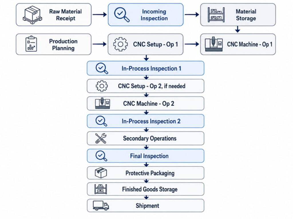
The goal is not to make the diagram overly complicated. The goal is to make it clear enough that a customer can understand how the part is produced and controlled.
What Process Parameters Should Be Identified?
Each operation should include enough detail to connect the process flow with the Control Plan and PFMEA. This usually includes the operation number, operation description, work center or machine identification, key characteristics being produced, and inspection requirements.
For example, instead of writing “Machine part,” a better description would be “CNC Mill: Rough profile and semi-finish pockets.” This gives the customer a clearer understanding of what actually happens at that stage.
Where Should Inspection Points Be Shown?
Inspection points should appear wherever product quality is verified. This may include receiving inspection, first-piece inspection, in-process inspection, last-piece inspection, final inspection, and subcontract receiving inspection.
| Type | When | Purpose | Method |
| First Piece | Start of production | Verify setup | Dimensional check |
| In-Process | During run | Monitor stability | SPC, sampling |
| Last Piece | End of production | Verify completion | Dimensional check |
| 100% | Critical features | Ensure all parts are good | Automated or manual |
| Patrol | Random intervals | System verification | Spot checks |
What Does a CNC Machining Process Flow Look Like?
What Is an Example of a Simple Turned Part Process Flow?
A simple turned part may only require one setup and a small number of operations. In this type of process, the flow is usually easy to show in table form.
| Step | Operation | Equipment | Inspection | Notes |
| 10 | Receive bar stock | Receiving | Visual, count | C36000 cert req’d |
| 20 | Incoming inspection | QC Lab | Chem, dim | Per MIL-I-45208 |
| 30 | Store raw material | Rack A-12 | None | FIFO rotation |
| 40 | Load bar feeder | Lathe L-05 | None | 12-ft bars |
| 50 | CNC Turn, complete | Lathe L-05 | In-process | Auto-inspection |
| 60 | First piece inspect | QC Station | Full layout | Setup approval |
| 70 | Run production | Lathe L-05 | SPC | Hourly samples |
| 80 | 100% deburr | Tumbler T-01 | Visual | 30 min cycle |
| 90 | Final inspection | CMM Room | Full dims | CMM program Q-156 |
| 100 | Package/ship | Shipping | Count, label | Bubble wrap |
What Is an Example of a Multi-Operation Milled Part Process Flow?
A more complex milled part may require multiple setups and inspections between machining operations. This is common when a part needs 4-axis machining or when different sides of the part must be machined separately.
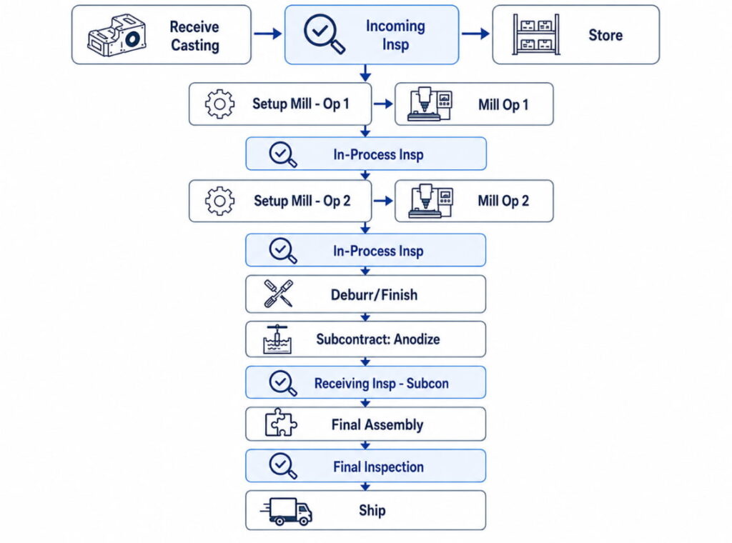
This type of process flow is useful because it shows not only the machining sequence, but also where inspections and subcontract processes take place.
How Should Complex Assemblies Be Shown?
For complex assemblies, it is usually better to create a master process flow. This master flow can reference separate component manufacturing flows, then show how the components move into subassembly, final assembly, and system-level testing.
This approach keeps the main process flow readable while still showing enough detail for customer review.
What Process Flow Diagram Format Should You Use?
When Should You Use a Text-Based Table?
A text-based table works well for simple parts, especially when the process has a limited number of steps. It is easy to prepare, easy to update, and useful when the customer accepts a simple format.
| Op # | Description | Work Center | Characteristics | Inspection |
| 010 | Receive Material | Receiving | N/A | Certificate |
| 020 | Incoming Insp | QC | Chemistry | Per spec |
| 030 | Store | Raw Stk | N/A | None |
| 040 | Turn Op 1 | CNC-01 | OD, lengths | SPC |
| 050 | Turn Op 2 | CNC-01 | Groove, threads | SPC |
| 060 | Deburr | Bench | Burr-free | 100% visual |
| 070 | Final Insp | QC | All dims | CMM |
| 080 | Ship | Shipping | Count | Verify PO |
When Should You Use a Flowchart Diagram?
A flowchart is the standard format for many PPAP submissions because it visually shows how the process moves from one step to another. It can be created using Microsoft Visio, Lucidchart, Draw.io, PowerPoint, Word shapes, or QMS software.
For best results, the flow should move left-to-right or top-to-bottom. Operation numbers should be included, decision branches should be visible, and inspection points should be easy to identify.
When Should You Use a Swimlane Diagram?
A swimlane diagram is useful when the process involves multiple departments or handoffs. For example, a part may move from receiving to production, then to quality control, back to production, and finally to shipping.
Example:
Department:
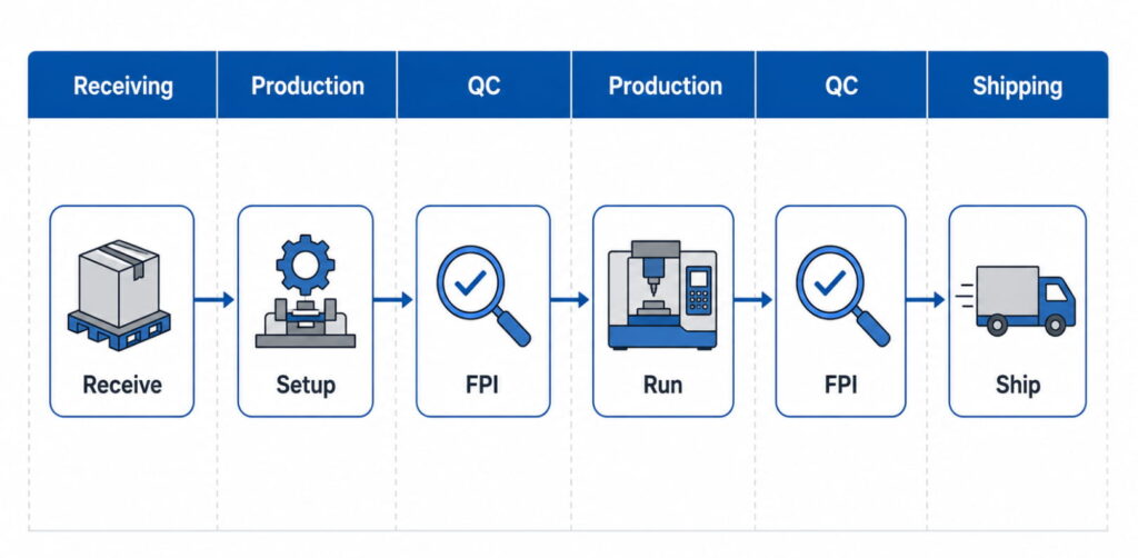
This format is especially useful for identifying responsibilities and preventing confusion between departments.
How Does the Process Flow Link to Other PPAP Documents?
Linking to Control Plan
Every operation in the process flow should have a matching entry in the Control Plan. For example, “Op 50: CNC Turn” in the process flow may correspond to Control Plan Lines 3–5, while “Op 60: In-Process Inspection” may correspond to Control Plan Line 6.
The operation numbers should match across documents. If the process flow and Control Plan use different numbering systems, customers may reject the PPAP submission because the documents do not appear aligned.
Supporting PFMEA?
The process flow provides the structure for the PFMEA. Each process step can become a PFMEA item because each step has potential failure modes. For example, a CNC turning operation may have risks related to incorrect dimensions, tool wear, poor surface finish, or wrong setup.
By using the process flow as the foundation, the PFMEA becomes easier to organize and more closely connected to the actual manufacturing process.
Connecting to Work Instructions?
The process flow shows the sequence of operations, while work instructions explain how each operation should be performed. For example, the process flow may show “CNC Mill Op 1,” while the work instruction explains the setup, tools, program, inspection method, and operator steps.
Referencing work instruction numbers on the process flow helps connect customer-facing documentation with shop floor execution.
What Common Mistakes Should You Avoid?
Missing Inspection Points
A process flow that only shows machining steps is incomplete. Customers want to see how quality is verified throughout the process. This means the diagram should include receiving inspection, in-process inspection, final inspection, and subcontract receiving inspection where applicable.
Vague Operation Descriptions
Descriptions such as “machine part” or “inspect part” are too general. They do not explain what is being produced, controlled, or verified. Clearer descriptions such as “CNC Mill: Rough profile, semi-finish pockets” or “CMM Inspection: Dimensions per Control Plan” make the process easier to understand.
Ignoring Rework Loops
A process flow should show what happens when non-conforming parts are found. If rework is possible, the flow should show how the part returns to the correct operation. If the part must be scrapped or held for disposition, that path should also be clear.
This helps customers see that the supplier has a controlled method for handling quality issues.
Inaccurate Scope
The process flow should include all operations from receipt to shipment, but it should also clearly identify which operations are subcontracted. For example, if anodizing is performed by an outside supplier, the flow should show the part leaving for subcontract processing, returning, and going through receiving inspection.
Diagram Not Matching the Actual Shop Floor Process
One of the biggest mistakes is creating a process flow only for PPAP paperwork. If the diagram does not match what actually happens on the shop floor, it can create audit findings and customer concerns.
The best method is to create the process flow by walking the actual process and confirming each step with production and quality personnel.
What Software Tools Can Be Used for Process Flow Diagrams?
Commercial QMS Software
| Software | Features | Cost |
| EtQ | Integrated QMS, PPAP module | $$$$ |
| IQS | Full APQP/PPAP support | $$$ |
| Intellect | Configurable workflows | $$$ |
| MasterControl | Document control + PPAP | $$$$ |
Diagramming Tools
| Tool | Best For | Cost |
| Microsoft Visio | Professional diagrams | $$ |
| Lucidchart | Collaboration, sharing | $-$$ |
| Draw.io | Free, capable | Free |
| SmartDraw | Templates, automation | $$ |
Can CAD/CAM Systems Help?
Some CAM systems can generate process documentation from programmed operations. Examples include Mastercam, GibbsCAM, Esprit, and FeatureCAM. These tools may be helpful for advanced manufacturers that want to connect CNC programming more closely with process documentation.
Southeast Asia Manufacturing Considerations
In Southeast Asia, CNC machining suppliers often manage customer documentation, shop floor communication, subcontract operations, and regional compliance requirements at the same time. A strong process flow diagram should reflect these realities clearly, especially when serving automotive, aerospace, medical, or industrial customers.
Multilingual Documentation Practices
In Southeast Asia, it is common for customer-facing documentation to be prepared in English while shop floor instructions are written in the local language. This can work well as long as the process flow and work instructions remain aligned.
Visual symbols, photos, and picture-based work instructions can also reduce confusion and make the process easier for operators to follow.
Subcontract Process Control
Subcontracting is common in CNC manufacturing, especially for heat treatment, plating, anodizing, grinding, and other specialized processes. These operations should not be hidden or treated as separate from the process flow.
The diagram should show the subcontract operation in sequence, include transportation steps, and include receiving inspection after the parts return. This proves that the supplier controls the quality of outsourced processes, not just in-house machining.
Thailand Automotive Supplier Requirements
For Thailand automotive manufacturing, suppliers often follow AIAG PPAP 4th Edition. IATF 16949 adoption is also increasing, while Thai Industrial Standards are becoming more aligned with international standards.
To support customer clarity, suppliers should use AIAG standard symbols, include metric and imperial units if the customer requires them, and maintain proper document control.
Who Creates the Process Flow Diagram?
The process flow diagram is usually created through collaboration. The Manufacturing Engineer defines the operations, sequence, and equipment. The Quality Engineer defines inspection points and Control Plan links. Production confirms that the flow matches the actual shop floor process, while the Quality Manager approves the final document.
Although several departments contribute, the Process Owner is usually Manufacturing Engineering.
Process Flow Diagram Detail and Maintenance
A process flow diagram should be detailed enough to show the complete process sequence, identify all inspection points, support the PFMEA, link to the Control Plan, and help the customer understand how the part is manufactured.
However, it should not become a full work instruction. The process flow explains what happens and in what order. The work instruction explains exactly how each task is performed.
Part-Specific vs Generic Process Flows
In most cases, each part number should have its own process flow, especially if the manufacturing route, inspection requirements, or customer requirements are different.
However, part families with identical processes may sometimes share a generic process flow. If this approach is used, any differences between parts must be clearly documented. For high-risk or critical parts, customers may still require part-specific process flows.
Updating Process Flows
Process flows should be updated whenever the manufacturing process changes. This includes new equipment, a different operation sequence, design changes, corrective actions, new inspection requirements, or customer-requested changes.
Even when there are no major changes, process flows should be reviewed regularly as part of the quality management system. Annual review is a common minimum practice.
PPAP Level 3 vs Level 5 Process Flow Requirements
The content of the Process Flow Diagram does not change based on PPAP submission level. The difference is how the document is submitted or reviewed.
For Level 3, the process flow is submitted with the rest of the PPAP package. For Level 5, the process flow is kept at the supplier’s facility and made available for customer review. The document itself should contain the same process information.
Why Would a Customer Reject a Process Flow Diagram?
A customer may reject a PPAP submission if the process flow does not match the Control Plan, PFMEA, or actual production process. Common problems include inconsistent operation numbers, missing inspections, different revision levels, or Control Plan steps that do not appear in the process flow.
The best way to prevent this is to use a cross-reference matrix and update all related PPAP documents together whenever the process changes.
Showing Subcontract Operations Clearly
Subcontract operations should be shown as part of the normal production sequence. They should be clearly labelled, for example, “Subcon: Heat Treatment” or “OUTSIDE: Plating.” The process flow should also show the movement to and from the subcontractor, followed by receiving inspection after the parts return.
Example:
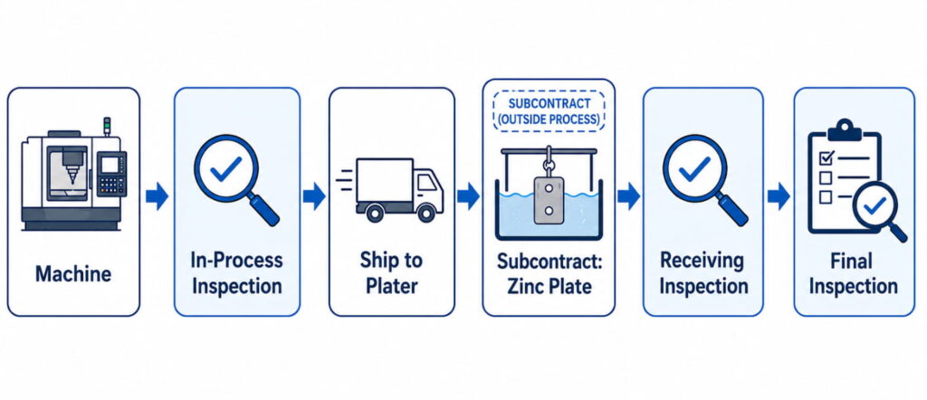
The receiving inspection after subcontracting is important because it confirms that the returned parts meet requirements before the process continues.
Process Flow Diagrams Beyond Automotive Manufacturing
Process flow diagrams are useful even when PPAP is not formally required. Aerospace manufacturers may use similar documentation through FAIR, medical manufacturers need strong process documentation under ISO 13485, and general manufacturers benefit from clearer process control and training.
Even without a customer requirement, a clear process flow can improve internal communication, reduce mistakes, support training, and make audits easier.
Handling Optional Operations in the Process Flow
Optional operations should be shown clearly so that operators, inspectors, and customers understand when they apply. This can be done using a decision diamond, such as “Rework Required?” or by noting “As Required” beside the operation.
For more complex situations, alternate process flows or footnotes may be used. The key is to avoid confusion. Anyone reading the diagram should understand when the optional step is needed and how it connects to the rest of the process.
Conclusion
A Process Flow Diagram is more than a required PPAP document. It is a practical tool that shows how a CNC machining supplier controls the full production journey from raw material receipt to final shipment. When the process flow is accurate, detailed, and aligned with the Control Plan and PFMEA, it gives customers confidence that the supplier understands both the part and the manufacturing process.
For CNC machining companies, a well-prepared process flow diagram can reduce PPAP rejection risk, improve audit readiness, strengthen internal communication, and make production responsibilities clearer. It also helps identify weak points in the process before they become quality issues.In competitive manufacturing markets, strong documentation can be a trust signal. Suppliers that can clearly explain their process, inspection strategy, subcontract controls, and document links are more likely to appear reliable, professional, and ready for demanding automotive, aerospace, medical, and industrial customers.
At Align Manufacturing, we understand that strong process documentation is just as important as the machining or casting process itself. As a Western-owned and operated sourcing and engineering company with operations across Thailand, Vietnam, and India, we help customers move from engineering drawings to reliable finished parts through processes such as investment casting, CNC machining, forging, stamping, and fabrication. Our experience with investment casting steel materials, precision machining, quality control, testing, and shipping allows us to support customers who need both technical manufacturing capability and clear documentation for demanding industrial projects.
What is Martensitic Steel? Strength, Structure, Grades, and Applications
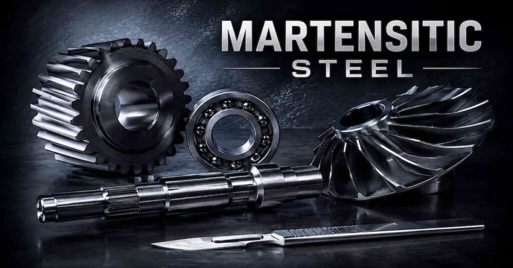
When engineers need exceptional strength without excessive weight, martensitic steel often becomes their material of choice. This specialised class of steel can deliver tensile strengths ranging from around 900 MPa to more than 1,700 MPa, making it one of the strongest commercially available steel varieties while still remaining practical for manufacturing.
Unlike conventional carbon steels or austenitic stainless grades, martensitic steel achieves its properties through a unique crystal structure and heat treatment process. The steel is heated, rapidly cooled, and often tempered to transform it from a softer, workable material into a hard, strong engineering material.
From electric vehicle battery enclosures to surgical instruments, martensitic steel has become important across industries where strength, hardness, wear resistance, and durability matter. This guide explains what martensitic steel is, how it works, where it is used, and how to decide whether it is the right material for your application.
What Is Martensitic Steel in Simple Terms?
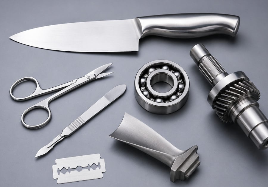
Martensitic steel is a type of steel that becomes very hard and strong through heat treatment. It is heated to form a high-temperature structure called austenite, then rapidly cooled through a process known as quenching. This rapid cooling traps carbon atoms inside the steel’s crystal structure, forming martensite.
In simple terms, martensitic steel is chosen when manufacturers need a material that can resist wear, carry high loads, and maintain strength in demanding conditions. It is commonly used in automotive safety parts, cutting tools, surgical instruments, turbine components, pump shafts, bearings, and other precision-engineered parts.
Martensitic stainless steel is a specific type of martensitic steel that contains enough chromium to provide corrosion resistance. However, its corrosion resistance is usually lower than austenitic stainless steels such as 304 or 316.
What Makes Martensitic Steel Different?
Body-Centered Tetragonal Crystal Structure

The defining feature of martensitic steel is its body-centered tetragonal, or BCT, crystal structure. This is the atomic arrangement that gives martensitic steel its high hardness and strength.
| Steel Type | Crystal Structure | Key Properties |
| Ferritic | Body-Centered Cubic (BCC) | Soft, magnetic, moderate strength |
| Austenitic | Face-Centered Cubic (FCC) | Non-magnetic, excellent corrosion resistance, not heat-treatable |
| Martensitic | Body-Centered Tetragonal (BCT) | Very hard, very strong, magnetic, heat-treatable |
In the BCT structure, iron atoms form a distorted cube-like pattern. One axis is stretched while the other two are compressed. This distortion happens when carbon atoms become trapped in the iron lattice during rapid cooling.
The trapped carbon creates internal strain inside the crystal structure. This strain makes it difficult for dislocations, which are tiny defects in the metal structure, to move. Since dislocation movement is what allows metals to deform, restricting that movement makes martensitic steel much harder and stronger.
It Forms Through Quenching
Martensitic steel begins as austenite, a high-temperature phase where carbon atoms are dissolved in the iron matrix. To form martensite, the steel must be cooled quickly enough to prevent softer structures such as ferrite, pearlite, or bainite from forming.
The quenching process usually involves four stages:
- Heating, or austenitizing: The steel is heated to around 815-900°C, depending on its carbon content and grade.
- Rapid cooling, or quenching: The hot steel is cooled quickly in water, oil, air, or polymer solutions.
- Martensitic transformation: Rapid cooling prevents carbon atoms from diffusing out of the structure.
- Final result: The steel forms hard martensite, often with a needle-like or plate-like microstructure.
The cooling speed is critical. If the steel cools too slowly, carbon atoms have time to move and form softer phases. The quenching medium is therefore selected based on the steel grade, the component shape, and the final properties required.
Its Composition Controls Its Final Performance
Martensitic steels typically contain carbon, chromium, and other alloying elements. Carbon is the primary hardening element, usually ranging from around 0.1% to 1.2%. Chromium is commonly used in martensitic stainless grades, usually between 11% and 18%, to improve corrosion resistance. Other elements such as molybdenum, vanadium, nickel, and manganese may be added to improve toughness, hardenability, wear resistance, or corrosion performance.
Carbon content has a major influence on the final hardness. Low-carbon martensitic steels, usually around 0.1% to 0.3% carbon, provide moderate hardness with better toughness and weldability. Medium-carbon grades, around 0.3% to 0.6%, provide a balanced combination of hardness and toughness. High-carbon grades, around 0.6% to 1.2%, offer maximum hardness and wear resistance, but they are also more brittle and more difficult to weld or form.
What Mechanical Properties Does Martensitic Steel Offer?
It Provides Very High Strength
Martensitic steel is used when high tensile strength is a priority. Some grades offer minimum tensile strengths from 900 MPa to more than 1,700 MPa.
| Grade | Minimum Tensile Strength | Typical Applications |
| 900M | 900 MPa | Structural components and general engineering |
| 1100M | 1,100 MPa | Automotive structural parts and machinery |
| 1300M | 1,300 MPa | High-stress components and performance parts |
| 1500M | 1,500 MPa | Safety-critical automotive and aerospace components |
| 1700M | 1,700 MPa | Armour, intrusion protection, and ultra-high-strength applications |
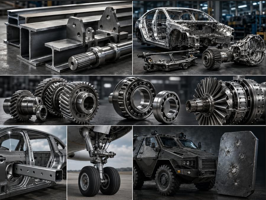
To put this into perspective, mild steel typically sits around 250-400 MPa, while many standard structural steels sit around 400-550 MPa. Martensitic steel can therefore provide much higher strength in thinner sections.
This is one reason it is valuable in automotive and electric vehicle applications. A component made from ultra-high-strength martensitic steel can sometimes be made thinner than an equivalent mild steel component while still carrying the required load.
It Can Achieve High Hardness
Martensitic steel can reach very high hardness levels after quenching. High-carbon martensitic grades can exceed 60 HRC on the Rockwell C scale, making them suitable for cutting tools, bearings, blades, valve components, and other wear-resistant applications.
However, high hardness also creates a trade-off. After quenching, martensitic steel can be brittle and prone to cracking under impact. To improve toughness, the material is usually tempered.
Tempering is a controlled reheating process, commonly carried out between 200°C and 700°C. It reduces hardness slightly but significantly improves toughness, making the steel more useful for structural and engineering applications. Lower tempering temperatures retain more hardness, while higher tempering temperatures produce softer but tougher material.
How Is Martensitic Steel Different from Other Stainless Steels?
Martensitic steel is different from austenitic and ferritic stainless steels because it can be hardened through heat treatment. Austenitic stainless steels, such as 304, are known for excellent corrosion resistance and weldability, but they cannot be hardened by heat treatment. Ferritic stainless steels, such as 430, are magnetic and corrosion-resistant, but they do not reach the same strength and hardness levels as martensitic grades.
This makes martensitic steel the preferred option when strength, hardness, and wear resistance are more important than maximum corrosion resistance.
| Property | Martensitic | Austenitic 304 | Ferritic 430 |
| Strength | Very high, often 900-1700 MPa | Moderate, around 515 MPa | Moderate, around 450 MPa |
| Hardness | Very high after heat treatment | Low to moderate | Moderate |
| Corrosion resistance | Moderate | Excellent | Good |
| Heat treatable | Yes | No | Limited |
| Magnetic | Yes | No | Yes |
| Weldability | Difficult | Excellent | Good |
| Common use case | Strength and wear resistance | Corrosion resistance and weldability | Cost-effective corrosion resistance |
The key point is that martensitic steel is not selected because it is the easiest stainless steel to weld or the most corrosion-resistant. It is selected because it offers a strong combination of hardness, strength, and wear resistance.
What Are the Common Martensitic Steel Grades?
Type 410 Stainless Steel
Type 410 is one of the most widely used martensitic stainless steels. It typically contains around 11.5% to 13.5% chromium and up to 0.15% carbon. It offers good corrosion resistance, moderate strength, and good machinability.
Common applications include cutlery, turbine blades, pumps, valves, fasteners, shafts, and general-purpose industrial components. Type 410 is often chosen because it is economical, widely available, and versatile.
Type 420 Stainless Steel
Type 420 contains around 12% to 14% chromium and a higher carbon content than Type 410. This gives it greater hardness and wear resistance.
It is commonly used for surgical instruments, knives, molds, dies, machine parts, and other products where edge retention or hardness is important. Type 420 is useful when the application needs better hardness than Type 410 but does not require the maximum wear resistance of higher-carbon grades.
Type 440C Stainless Steel
Type 440C contains around 16% to 18% chromium and 0.95% to 1.20% carbon. It is one of the hardest martensitic stainless steel grades and offers excellent wear resistance.
Common applications include ball bearings, valve seats, cutting tools, surgical tools, and premium knife blades. It is a strong choice when high hardness and wear resistance are more important than formability or weldability.
1.4057 / AISI 431 Stainless Steel
1.4057, also known as AISI 431, contains chromium, nickel, and carbon. The nickel addition improves toughness and makes the grade more suitable for marine and high-stress applications.
Typical uses include marine hardware, aircraft fittings, pump shafts, and propeller shafts. It is often used where a combination of strength, toughness, and moderate corrosion resistance is needed.
1.4418 Stainless Steel
1.4418 is a low-carbon martensitic stainless steel with improved weldability and corrosion resistance. It is used in applications such as hydroelectric turbines, propeller shafts, and pump components.
This grade is useful when a component requires high strength but also needs better weldability than traditional high-carbon martensitic grades.
Which Martensitic Steel Grade Should You Choose?
The best grade depends on the application, strength requirement, corrosion exposure, and manufacturing method.
| Requirement | Recommended Martensitic Grade | Why It Fits |
| General-purpose strength and corrosion resistance | Type 410 | Economical, widely available, and suitable for pumps, valves, shafts, and turbine parts |
| Better hardness and edge retention | Type 420 | Higher carbon content improves hardness and wear resistance |
| Maximum wear resistance | Type 440C | High carbon and chromium content support very hard applications |
| Marine strength and toughness | 1.4057 / AISI 431 | Nickel improves toughness and performance in marine environments |
| Better weldability with high strength | 1.4418 | Lower carbon improves weldability while maintaining strength |
| Automotive crash protection | 1300M-1700M grades | Ultra-high tensile strength supports lightweight safety structures |
| EV battery protection | 1500M-1700M grades | Strong intrusion resistance with thinner material sections |
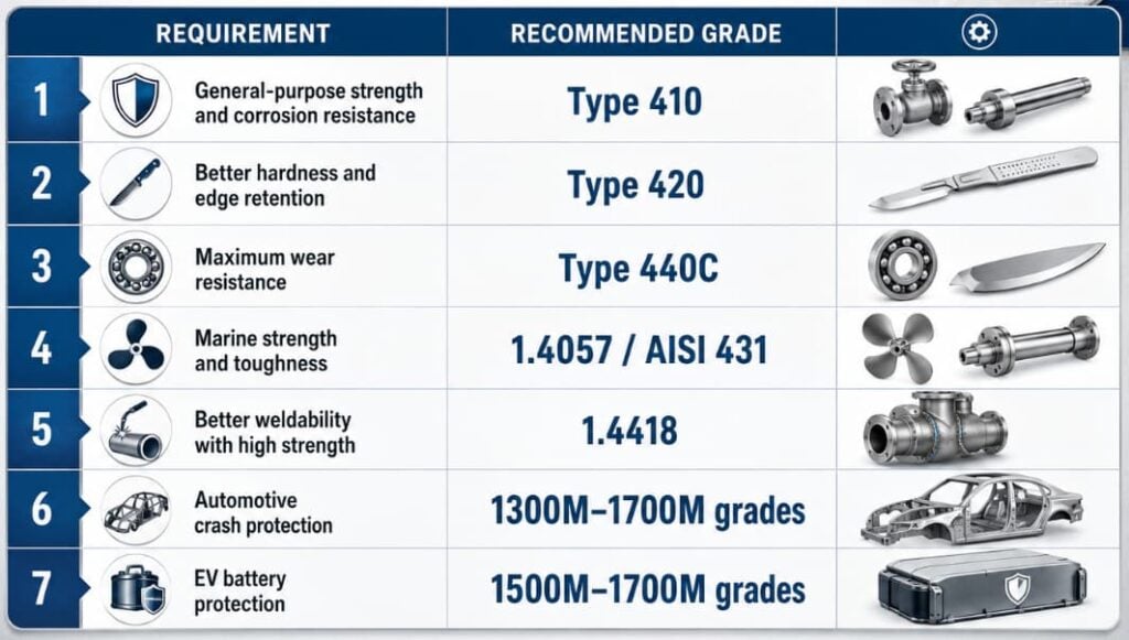
This selection table is a starting point. Final material choice should always consider part geometry, heat treatment, forming requirements, corrosion exposure, welding requirements, and cost.
Where Is Martensitic Steel Used?
Automotive and Electric Vehicles
The automotive sector is one of the most important users of martensitic steel, especially in structural safety components. Its high strength allows manufacturers to improve crash protection while reducing unnecessary weight.
Common automotive applications include:
- Door beams
- Bumper systems
- Sill reinforcements
- B-pillars
- Cross members
- Safety cage components
- Battery enclosure protection in electric vehicles
In electric vehicles, battery protection is especially important. Martensitic steel grades such as 1500M and 1700M can help protect battery packs from intrusion while allowing thinner, lighter structures. This is valuable because reducing vehicle weight can help improve efficiency and range.
Aerospace Applications
Aerospace uses martensitic steels selectively where high strength, wear resistance, and heat treatability are important. Typical applications include landing gear components, fasteners, control surface hinges, engine mounts, and other high-stress parts.
Aerospace materials must be selected carefully because strength, fatigue resistance, corrosion exposure, and weight all matter. Martensitic steel is not used everywhere in aircraft, but it can be valuable where high mechanical performance is required.
Cutlery, Blades, and Surgical Instruments
Martensitic stainless steel is widely used in knives, razor blades, surgical instruments, and industrial cutting tools because it can be hardened and sharpened. Grades such as 420 and 440C are especially common in applications where edge retention and wear resistance are important.
For surgical instruments, the material must balance hardness, precision, corrosion resistance, and sterilisation requirements. Martensitic stainless grades are useful because they can achieve the sharpness and hardness needed for cutting and precision use.
Marine and Oil & Gas
Martensitic stainless steels are used in marine and oil and gas applications where components require strength, toughness, and moderate corrosion resistance. Grades such as 1.4057 / AISI 431 are used in pump shafts, propeller shafts, valve parts, and offshore hardware.
However, martensitic stainless steel is not always suitable for highly corrosive environments. In aggressive chloride-rich conditions, austenitic, duplex, or precipitation-hardening stainless steels may be better options.
Industrial Machinery and Tooling
Martensitic steel is also used in industrial machinery, molds, dies, bearings, valves, shafts, and wear parts. Its ability to be hardened makes it suitable for components that experience repeated contact, friction, or mechanical loading.
In these applications, heat treatment control is especially important. The wrong hardness or toughness level can lead to premature wear, cracking, distortion, or failure.
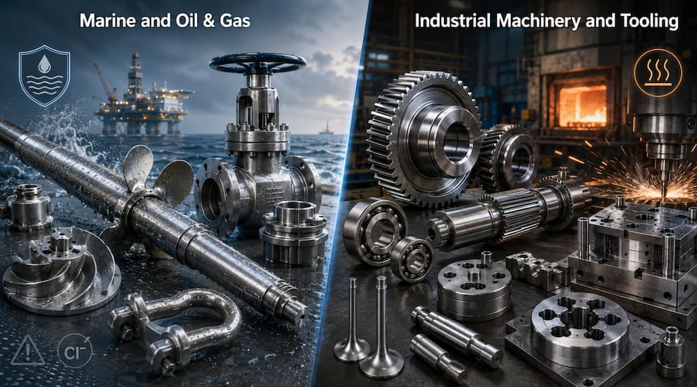
What Are the Advantages and Limitations of Martensitic Steel?
Its Main Advantages Are Strength, Hardness, and Wear Resistance
Martensitic steel offers several advantages for demanding applications. Its biggest benefit is its ability to reach high strength and hardness through heat treatment. This makes it useful for parts that must resist wear, impact, deformation, cutting forces, or high mechanical loads.
It can also support lightweight design. In some applications, ultra-high-strength martensitic steel allows manufacturers to use thinner material sections without losing structural performance. This is valuable in automotive, aerospace, and electric vehicle design.
Another advantage is customisability. Through heat treatment and tempering, manufacturers can adjust the final balance of hardness, strength, and toughness to suit the application.
Its Main Limitations Are Brittleness, Welding Difficulty, and Moderate Corrosion Resistance
Martensitic steel also has limitations. High-carbon martensitic grades can become brittle if they are not properly tempered after quenching. This can lead to cracking or poor impact performance.
Welding can also be difficult because the heat-affected zone may harden during cooling, creating brittle areas that are prone to cracking. Preheating, low-hydrogen welding processes, and post-weld heat treatment may be required.
Corrosion resistance is another limitation. Martensitic stainless steels generally provide moderate corrosion resistance, but they usually do not match the corrosion performance of austenitic stainless steels such as 304 or 316. For harsh chemical, marine, or chloride-rich environments, another stainless steel family may be more appropriate.
What Manufacturing Considerations Matter for Martensitic Steel?
Heat Treatment Must Be Carefully Controlled
Martensitic steel’s properties depend heavily on proper heat treatment. The basic cycle involves austenitizing, quenching, tempering, and cooling.
If the steel is not heated properly, it may not transform correctly. If quenching is too slow, the steel may not achieve the required hardness. If quenching is too aggressive, the component may distort or crack. If tempering is insufficient, the steel may remain too brittle for service.
This is why martensitic steel parts often require close control of heat treatment temperature, cooling rate, and post-treatment inspection.
Machining Is Easier Before Hardening
Martensitic steel is generally easier to machine in the annealed condition. Once hardened, it becomes more difficult to cut and may require carbide tooling, grinding, or other finishing methods.
For this reason, many manufacturers complete most machining operations before final hardening. This helps reduce tool wear, improve dimensional accuracy, and lower production difficulty.
Welding Requires Extra Care
Welding martensitic steel requires careful planning. The main challenge is the heat-affected zone, which can harden and become brittle during cooling. This increases the risk of cracking.
Good welding practice may include preheating, using low-hydrogen welding consumables, maintaining interpass temperature, and applying post-weld heat treatment. For high-carbon grades, welding may be impractical, and alternative joining methods such as bolting, mechanical fastening, or adhesive bonding may be considered.
When Should You Use Martensitic Steel?
Martensitic steel is a good choice when the application requires high strength, high hardness, wear resistance, and heat-treatable performance. It is also suitable when magnetic properties are acceptable and moderate corrosion resistance is enough.
It is especially useful for components that need to resist deformation, cutting, impact, or wear. Examples include automotive safety structures, cutting tools, surgical instruments, pump shafts, valves, bearings, turbine parts, and EV battery protection components.
Martensitic steel may also be suitable when weight reduction is important. Because ultra-high-strength grades can carry high loads, engineers may be able to reduce material thickness in selected designs.
When Should You Avoid Martensitic Steel?
Martensitic steel may not be the best choice when the application requires maximum corrosion resistance, extensive welding, high ductility, or non-magnetic properties.
For highly corrosive environments, austenitic stainless steel, duplex stainless steel, or precipitation-hardening stainless steel may be better. For applications requiring excellent weldability, austenitic stainless steels are usually easier to work with. For low-cost applications where high strength is not needed, carbon steel may be more economical.
Martensitic steel should also be avoided when the manufacturing process cannot properly control heat treatment. Since its final properties depend heavily on quenching and tempering, poor process control can lead to cracking, distortion, brittleness, or inconsistent performance.
How Should Engineers Select Martensitic Steel?
Material selection should begin with the performance requirement. Engineers should first define the load, tensile strength, hardness, wear resistance, and toughness required for the component. The next step is to assess the operating environment, including corrosion exposure, temperature, moisture, chemicals, and impact conditions.
Manufacturing requirements should also be reviewed. If the part requires extensive welding, complex forming, tight machining tolerances, or post-heat-treatment finishing, these factors may influence the grade selection.
A practical decision process should consider:
- Strength requirement: What load must the part carry?
- Hardness requirement: Does the part need edge retention or wear resistance?
- Corrosion exposure: Will the part face moisture, chemicals, salt, or high temperatures?
- Manufacturing route: Will the part be machined, formed, welded, heat treated, or ground?
- Toughness requirement: Does the part need to resist impact or fatigue?
- Cost balance: Is the performance benefit worth the material and processing cost?
The best grade is not always the hardest grade. In many applications, the best choice is the grade that offers the right balance of strength, toughness, corrosion resistance, manufacturability, and cost.
Why Does Martensitic Steel Remain Important?
Martensitic steel occupies a valuable position in the materials world. It delivers high strength and hardness while still offering the practical advantages of steel, including machinability in the annealed condition, heat treatability, magnetic behaviour, and availability across many grades.
Its importance is also increasing because modern industries need materials that can support lighter, stronger, and safer designs. Automotive lightweighting, electric vehicle battery protection, precision tooling, and advanced manufacturing all benefit from materials that can provide high strength without excessive bulk.
The relationship between composition, quenching, tempering, and final properties makes martensitic steel highly adaptable. Whether the priority is maximum strength, balanced toughness, wear resistance, or moderate corrosion resistance, martensitic steel offers practical options for demanding engineering challenges.
Conclusion
Because martensitic steel performance depends heavily on grade selection, heat treatment, and manufacturing method, choosing the right production partner matters. Align Manufacturing helps customers evaluate whether martensitic steel is suitable for their component, or whether another steel, stainless steel, aluminium, or specialty alloy may be a better fit.
For companies looking for cost-effective, high-quality precision manufacturing, Align Manufacturing offers engineering-focused support and dependable production capabilities from Thailand. If your project requires strong, wear-resistant, or precision-machined components, our team can help you move from material selection to finished parts with confidence.
Align Manufacturing provides precision metal fabrication in Thailand and CNC machining services for companies that need reliable metal components for demanding applications. For projects involving martensitic steel, our team can support material selection, manufacturability review, machining planning, tolerance control, and production feasibility.
Related Resources:
- Grades of Stainless Steel: Types, Properties, and Applications
- Stainless Steel: Strength and Corrosion Resistance
- Tempering vs Hardening: What’s the Difference?
Frequently Asked Questions
Is martensitic steel stainless steel?
Martensitic steel can be stainless steel if it contains enough chromium, usually around 11% to 18%. Martensitic stainless steels combine heat-treatable strength with moderate corrosion resistance.
Is martensitic steel magnetic?
Yes, martensitic steel is generally magnetic in both the annealed and hardened conditions. This is one of the features that separates it from many austenitic stainless steels.
Is martensitic steel stronger than stainless steel?
Martensitic steel is stronger than many common stainless steels, especially austenitic grades such as 304. However, it usually has lower corrosion resistance than austenitic stainless steel.
Can martensitic steel be welded?
Martensitic steel can be welded, but it requires care. Preheating, low-hydrogen welding processes, and post-weld heat treatment may be needed to reduce cracking risk and restore toughness.
What is the main weakness of martensitic steel?
The main weakness of martensitic steel is that it can become brittle if not properly heat treated. It also has more difficult weldability and lower corrosion resistance than many austenitic stainless steels.
What is the difference between martensitic and austenitic stainless steel?
Martensitic stainless steel can be hardened through heat treatment and is usually magnetic. Austenitic stainless steel has better corrosion resistance and weldability, but it cannot be hardened by heat treatment and is usually non-magnetic.
What is the difference between martensitic and ferritic stainless steel?
Both martensitic and ferritic stainless steels are generally magnetic. The main difference is that martensitic steel can be hardened through heat treatment, while ferritic stainless steel has lower strength and is not normally heat-treatable in the same way.
Forging Aluminum vs Steel: Strength, Weight, and Cost
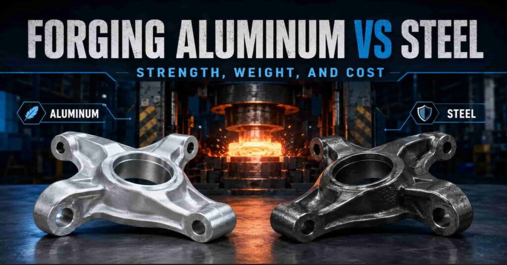
Every manufacturing decision carries weight, sometimes literally. When procurement engineers and product designers face the critical choice between forged aluminum and forged steel, they’re not just selecting a material. They’re defining performance parameters, cost structures, supply chain requirements, and ultimately, product success in competitive markets.
This comprehensive analysis provides the data-driven framework manufacturing professionals need to make informed material specification decisions. Whether you’re sourcing components for aerospace systems, automotive assemblies, or marine equipment, understanding the nuanced trade-offs between aluminum and steel forgings will position your projects for optimal outcomes.
What Is Drop Forging and Why Does It Matter?
Before diving into material comparisons, it’s essential to understand why drop forging matters. Unlike casting, which can introduce porosity and inconsistent grain structures, drop forging shapes metal billets through controlled compression and deformation.
The Process Improves Strength and Durability
The drop forging process begins with a metal billet being heated to the optimal forging temperature. Once heated, a high-pressure hammer or press shapes the material into a die. This controlled compression causes the grain structure to align with the component’s shape, resulting in superior mechanical properties, enhanced durability, and a refined microstructure.
This process fundamentally improves strength, fatigue resistance, and impact absorption, regardless of whether aluminum or steel serves as the base material. The forging advantage applies to both, but each material responds differently to the process, creating distinct performance profiles.
Why Is Aluminum Lighter Than Steel in Forging Applications?
Aluminum Offers a Major Weight Advantage
Aluminum’s most celebrated characteristic in manufacturing circles is its density, which is approximately one-third that of steel. This isn’t merely a specification point; it’s a transformational advantage for applications where every gram matters.
Key density comparison:
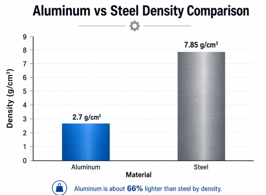
- Aluminum: 2.7 g/cm³
- Steel: 7.85 g/cm³
- Weight reduction: ~66% when switching from steel to aluminum
The Weight Difference Creates Real-World Benefits
In aerospace applications, this weight difference translates directly to fuel efficiency and payload capacity. A structural component weighing 30kg in steel becomes approximately 10kg in aluminum, resulting in a 20kg saving that compounds across thousands of parts in modern aircraft.
Transportation sector benefits include:
- Automotive: Reduced unsprung weight improves handling and fuel economy
- Aerospace: Every kilogram saved equals significant lifetime fuel savings
- Marine: Lower displacement improves vessel speed and efficiency
- Electric vehicles: Extended range through weight reduction
Aluminum Is Best When Weight Matters Most
Aluminum should be prioritised when mobility, transportation efficiency, and handling are important. It is especially useful when component weight affects overall system performance or when fuel costs represent a significant operational expense.
Is Steel Stronger Than Aluminum in Forged Components?
Steel Has Higher Absolute Strength
Steel maintains its reputation for raw strength, and deservedly so. In absolute terms, forged steel components withstand higher loads and stresses than their aluminum counterparts.
Tensile strength comparison:
- Forged steel: 500–2,000 MPa, depending on alloy and heat treatment
- Forged aluminum: 200–600 MPa, depending on alloy and temper
However, this comparison becomes more nuanced when examining strength-to-weight ratio, a critical metric for design engineers.
Aluminum Competes Through Strength-to-Weight Ratio
When normalised for weight, high-performance aluminum alloys approach and sometimes exceed steel’s performance. This is why aerospace manufacturers extensively use aluminum despite steel’s higher absolute strength.
Specific strength comparison:
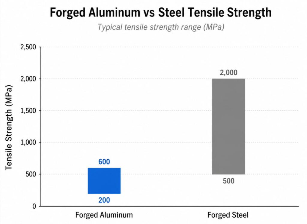
- High-strength aluminum alloys: 150–220 kN·m/kg
- Medium-carbon steel: 65–130 kN·m/kg
For equivalent weight budgets, aluminium often delivers superior structural performance.
Fatigue Resistance Depends on the Application
Forged components typically face cyclic loading, making fatigue resistance crucial. Forged aluminum performs well in high-cycle fatigue applications, especially with alloys such as 7075 and 7050. It is also well-suited for vibrating environments.
Forged steel, on the other hand, offers exceptional endurance limits in many alloy grades. It delivers consistent performance under repeated stress and is usually preferred for high-load, low-cycle applications.
How Do Aluminum and Steel Compare for Corrosion Resistance?
Aluminum Has Natural Corrosion Protection
Aluminum possesses an inherent corrosion resistance that steel cannot match without additional treatments. When exposed to oxygen, aluminum forms a thin, hard oxide layer that protects the underlying metal from further oxidation.
This oxide layer is valuable because it is self-healing, permanent, and effective in most atmospheric and marine environments. Scratches naturally re-oxidize, meaning the protection does not require constant reapplication or maintenance.
This makes aluminum suitable for:
- Marine applications and coastal installations
- Outdoor architectural components
- Food processing equipment
- Chemical processing environments
Steel Requires Additional Protection
Steel requires active corrosion protection through methods such as galvanizing, powder coating, paint systems, or plating. Stainless steel is another option, but it usually involves higher material costs, reduced machinability, and different forging characteristics.
Steel components also require ongoing inspection and maintenance of protective systems. Damage to coatings creates vulnerability points where corrosion can start and spread, sometimes invisibly until significant damage has occurred.
Which Material Is More Cost-Effective: Forged Aluminum or Forged Steel?
Steel Has Lower Raw Material Costs
At first glance, aluminum appears more expensive than steel.
Approximate raw material pricing:
- Aluminum: $2.50–4.00 per kg
- Steel: $0.50–1.50 per kg
However, material cost represents only one component of total cost of ownership.
Aluminum Can Reduce Processing Costs
Aluminum often offsets its higher raw material cost through easier machining and lower processing requirements. It can be machined faster, causes less tool wear, consumes less energy during processing, and makes it easier to achieve tight tolerances.
Steel, by contrast, usually requires slower machining, higher tooling costs, greater energy consumption, and may need post-forging heat treatment.
Finished Part Cost Can Favor Aluminum
For complex components requiring significant machining after forging, aluminum’s superior machinability can offset its higher raw material cost.
Example:
- Steel forging: $100 material + $300 machining = $400 total
- Aluminum forging: $150 material + $150 machining = $300 total
In this example, the aluminum component costs 25% less despite the material itself being more expensive.
Where Are Aluminum and Steel Forgings Used Across Industries?
Aerospace Strongly Favors Aluminum
Aerospace represents the ultimate proving ground for aluminum forgings. The sector’s strict weight requirements make aluminium the dominant choice for many components.
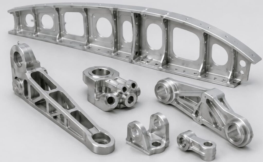
Typical aerospace applications include:
- Wing spars and ribs
- Fuselage frames
- Landing gear components
- Control surfaces
- Engine mounts
Common aerospace-grade aluminum alloys include 7075 for high strength-to-weight ratio, 7050 for toughness and stress corrosion resistance, and 2024 for fatigue resistance in wing and fuselage applications.
Automotive Manufacturing Uses Both Materials
Modern vehicles use both aluminum and steel strategically. Steel remains dominant in structural safety components, high-stress suspension parts, engine and transmission components, and cost-sensitive high-volume parts.
Aluminum is increasingly used for body panels, wheels, engine blocks, heads, and suspension components where weight reduction, thermal efficiency, and handling improvement are important.
Marine Applications Often Favor Aluminum
Marine environments heavily favor aluminum because of its corrosion resistance. It is commonly used for smaller vessel hull structures, superstructures, deck components, masts, rigging, and engine components.
Steel remains important in marine applications where heavy structural strength is needed, such as large vessel hulls, propeller shafts, anchoring systems, and high-load deck equipment.
Industrial Equipment Selection Depends on Performance Needs
Industrial applications typically prioritise strength and durability over weight. Steel is often preferred for heavy machinery components, press frames and beds, gear blanks, and high-load bearing housings.
Aluminum is becoming more common in robotics, conveyor systems, pneumatic equipment, and electronics enclosures where weight reduction, energy efficiency, portability, and heat dissipation matter.
How Should You Choose Between Aluminum and Steel Forgings?
Aluminum Is Better for Lightweight and Corrosion-Resistant Applications
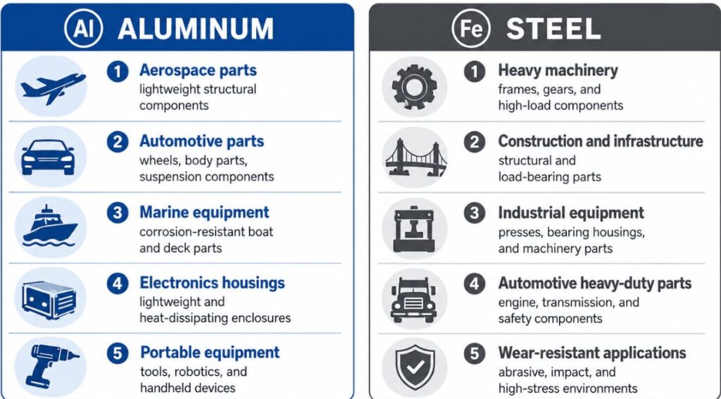
Aluminium should be prioritised when weight is critical, corrosion resistance is required, machining costs dominate, or thermal performance matters. It is especially suitable for transportation applications, aerospace components, handheld equipment, racing vehicles, marine environments, chemical exposure, and components with complex geometries.
Steel Is Better for Strength, Wear Resistance, and Cost-Sensitive Applications
Steel should be prioritised when absolute strength, wear resistance, cost sensitivity, or established supply chains matter most. It is often the better choice for heavy load-bearing components, safety-critical structures, high-impact applications, bearing surfaces, abrasive environments, and high-volume production.
What Forging Process Factors Should Engineers Consider?
Aluminum Requires Lower Forging Temperatures
Aluminum forging usually takes place at around 350–500°C. This lower temperature means less energy input, faster heating and cooling cycles, and reduced thermal stress on tooling.
Steel forging typically takes place at around 1,100–1,250°C. This requires higher energy consumption, longer heating cycles, and greater thermal stress on equipment.
Temperature Affects Die Life and Tooling Costs
The temperature difference between aluminum and steel has a major impact on tooling economics. Aluminum’s lower forging temperature generally extends die life, reduces maintenance frequency, lowers replacement costs, and allows higher production volumes per die set.
Steel forging usually creates more thermal fatigue, requires more frequent maintenance, involves higher tooling investment, and may require die replacement more often.
How Sustainable Are Aluminum and Steel Forgings?
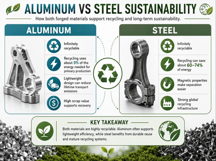
Both Materials Are Highly Recyclable
Both aluminum and steel offer excellent recyclability, but they differ in energy savings and recovery characteristics.
Aluminum is infinitely recyclable without quality loss, and recycling requires only around 5% of the energy needed for original production. It also has well-established recycling infrastructure and high scrap value, which encourages recovery.
Steel is also infinitely recyclable. Recycling steel saves around 60–74% of energy, and its magnetic properties make separation easier. It also benefits from established global recycling markets.
Lifecycle Impact Depends on the Application
Steel may have higher per-kg CO₂ emissions, while aluminum has an energy-intensive initial production process. However, in lightweight transportation applications, aluminum’s weight savings can result in lower lifetime emissions despite its higher production footprint.
How Should Aluminum and Steel Forgings Be Tested for Quality?
Both Materials Require Rigorous Testing
Both aluminum and steel forgings require careful quality verification. Common non-destructive testing methods include ultrasonic testing for internal defects, magnetic particle inspection for surface cracks, dye penetrant inspection for surface-breaking defects, and X-ray inspection for complex geometries.
Aluminum and Steel Have Different Testing Priorities
Aluminum-specific checks often focus on stress corrosion cracking susceptibility, heat treatment verification, and surface finish requirements.
Steel-specific checks often focus on hardness testing after heat treatment, microstructure verification, and temper and toughness validation.
What Are the Future Trends in Aluminum and Steel Forging?
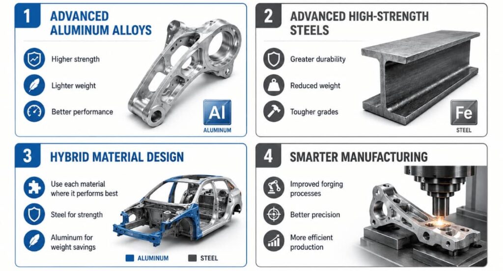
Aluminum Alloys Are Becoming Stronger
Research continues to develop aluminum alloys with improved performance. Emerging developments include scandium-aluminum alloys for exceptional strength, aluminum-lithium alloys for further weight reduction, nanostructured aluminum for enhanced properties, and improved recycling processes.
Steel Grades Are Also Advancing
Steel development focuses on achieving higher strength without major weight penalties. Advanced high-strength steels include dual-phase steels, transformation-induced plasticity steels, and twinning-induced plasticity steels.
Hybrid Material Approaches Are Growing
Innovative designs increasingly combine both materials. Multi-material structures may use steel cores with aluminum skins, strategic material placement, optimized strength-to-weight ratios, and a better balance between cost and performance.
Conclusion
The aluminum versus steel forging decision defies simple answers. Each material offers distinct advantages that align with specific application requirements, cost structures, and performance priorities.
Aluminum’s main advantages are light weight, corrosion resistance, machinability, and excellent strength-to-weight ratio. This makes it the optimal choice for transportation, aerospace, and weight-sensitive applications.
Steel’s main strengths are absolute strength, cost efficiency, wear resistance, and established supply chains. This makes it the preferred material for heavy-duty industrial, safety-critical, and high-volume applications.
Successful procurement engineers and product designers recognize that material selection represents a systems decision, not merely a material specification. By analyzing weight requirements, corrosion exposure, machining needs, volume economics, and performance priorities, manufacturers can confidently specify the optimal material for their applications. The forged component’s success depends not just on the material chosen, but on how well that material aligns with the application’s unique demands.
Here at Align Manufacturing, we help overseas companies source high-quality forged and engineered metal components from trusted manufacturing locations across Thailand, Vietnam, and India. As an operated manufacturing partner with local teams on the ground, we combine communication and project management with regional production expertise. For businesses searching for Forging In Thailand solutions, we provide a practical route to cost-effective, reliable, and customized forged components while helping reduce over-reliance on a single sourcing market.