Posts by Align Manufacturing
Material Certifications and IMDS Integration for Manufacturing Suppliers
Introduction: The Documentation Imperative
In modern manufacturing supply chains, producing quality parts is no longer sufficient, suppliers must prove quality through comprehensive documentation. Material certifications and the International Material Data System (IMDS) have become gatekeepers to doing business with automotive, aerospace, and medical OEMs. Understanding these requirements isn’t just about compliance; it’s about market access.
This guide demystifies material certification requirements and IMDS integration, providing actionable frameworks for suppliers seeking to meet and exceed their customers expectations.
Understanding Material Certifications
Types of Material Certifications
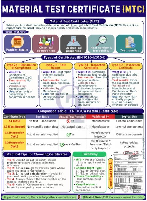
1. Mill Test Report (MTR) / Mill Certificate
The foundational document from the raw material producer:
| Information Included | Purpose |
| Heat/lot number | Traceability |
| Chemical composition | Alloy verification |
| Mechanical properties | Performance validation |
| Production date | Age-sensitive materials |
| Specification compliance | Standard conformance |
| Mill identification | Source verification |
2. Certificate of Compliance (C of C)

Supplier declaration that material meets specified requirements:
- May be based on MTR review
- Typically issued by distributor or converter
- Less comprehensive than full MTR
3. Certificate of Analysis (C of A)
Detailed chemical composition analysis:
- Element-by-element breakdown
- May include trace element reporting
- Often required for critical applications
4. Third-Party Inspection Certificates
Independent verification by accredited bodies:
- SGS, Bureau Veritas, TÜV, Lloyd’s Register
- Often required for international shipments
- Adds credibility and reduces customer inspection
Industry-Specific Certification Requirements
Automotive (IATF 16949)
| Document | Requirement | Retention |
| Material certifications | Full MTR for all production materials | Production life + 1 year |
| PPAP submissions | PSW with material data | Current + 1 revision |
| IMDS reporting | 100% of supplied materials | Indefinite |
| MSDS/SDS | Current safety data sheets | Current version + 30 years |
| RoHS/REACH | Compliance declarations | Current + 5 years |
Aerospace (AS9100 / AS9120)
| Document | Requirement | Retention |
| Material certifications | Full chemical and mechanical | 40 years minimum |
| Test reports | All testing performed | 40 years minimum |
| Supplier certifications | Approved source documentation | Duration of approval |
| Traceability records | Heat/lot to finished part | 40 years minimum |
| NADCOM / customer special | Process certifications | Per customer requirements |
Medical (ISO 13485)
| Document | Requirement | Retention |
| Biocompatibility | ISO 10993 testing | Device lifetime + 2 years |
| Material certifications | Full traceability | Device lifetime + 2 years |
| Sterilization validation | Gamma, EO, or autoclave data | Device lifetime + 2 years |
| Change control | Material change notifications | Indefinite |
Reading and Validating Mill Test Reports
Key Elements to Verify
1. Specification Alignment
Compare MTR specification to purchase order:
| Purchase Order Spec | MTR Claim | Verification |
| ASTM B16 | ASTM B16 Rev 2021 | Match exact revision |
| C36000 | C36000 | Verify UNS number |
| H02 Temper | H02 | Confirm temper |
| 1/2″ diameter | 0.500″ | Check dimensional |
2. Chemical Composition Analysis
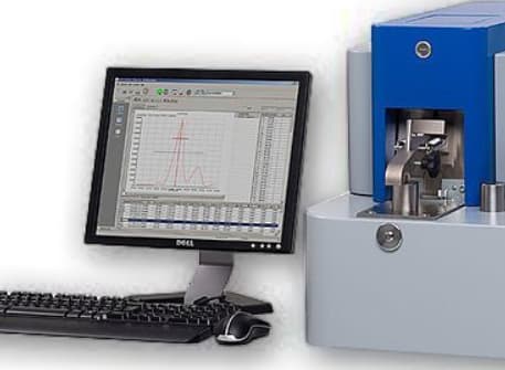
Typical brass composition table from MTR:
| Element | Specification Range | MTR Result | Status |
| Copper (Cu) | 60.0-63.0% | 61.8% | ✓ Accept |
| Lead (Pb) | 2.5-3.7% | 3.1% | ✓ Accept |
| Iron (Fe) | Max 0.35% | 0.12% | ✓ Accept |
| Zinc (Zn) | Remainder | 34.5% | ✓ Accept |
Red Flags:
- Elements outside specification range
- Missing required elements
- “Typical values” instead of actual test results
- No test method cited (e.g., ASTM E415 for spectroscopy)
3. Mechanical Property Verification
| Property | Specification | MTR Result | Tolerance |
| Tensile Strength | 58,000 PSI min | 62,400 PSI | +9% |
| Yield Strength | 45,000 PSI min | 48,200 PSI | +7% |
| Elongation | 25% min | 28% | +12% |
| Hardness | 80-90 HRB | 85 HRB | Mid-range |
4. Traceability Elements
Verify the MTR connects to your material:
- Heat number matches material marking
- Quantity received matches MTR quantity (or is subset)
- Date aligns with production schedule
The IMDS System Explained
What is IMDS?
The International Material Data System is the automotive industry’s global standard for collecting and managing material information:
- Created by: OEM consortium (Audi, BMW, Daimler, EDS, Ford, Opel, Porsche, VW, Volvo)
- Purpose: Track substances of concern; meet ELV, REACH, and other regulations
- Scope: All materials and substances in automotive products
- Current: Over 100,000 users; 400,000+ companies
Regulatory Drivers
| Regulation | Region | IMDS Role |
| ELV Directive 2000/53/EC | EU | Track and report recyclability; banned substance compliance |
| REACH | EU | SCIP database integration; SVHC reporting |
| China Standard GB/T | China | Material substance disclosure |
| K-REACH | Korea | Similar to EU REACH |
| Proposition 65 | California | Substance disclosure for warnings |
| GADSL | Global | Global Automotive Declarable Substance List compliance |
IMDS Structure
The Hierarchy
MDS (Material Data Sheet)
Each Node Contains:
- Identification (part number, name, weight)
- Classification (IMDS code)
- Application (where used in vehicle)
- Substances with CAS numbers and weights
Supplier IMDS Requirements
Who Must Report
| Tier | Responsibility |
| Tier 1 | Report complete assemblies to OEM |
| Tier 2 | Report components to Tier 1 |
| Tier 3+ | Report materials to upstream customers |
| Material Suppliers | Create base material MDSs |
Data Requirements
| Element | Required Information |
| Component name | As on drawing/PBOM |
| Part number | Customer part number |
| Weight | Grams (accurate to 0.001g for small parts) |
| Material classification | IMDS standard codes |
| Substances | All >0.1% by weight (REACH threshold) |
| CAS numbers | Chemical Abstracts Service registry |
| Recyclability | Percentage recyclable content |
Creating IMDS Entries
Step-by-Step Process
Step 1: Gather Information
Required data collection:
- Complete Bill of Materials (BOM)
- Material certifications for all materials
- Weights for each component and material
- Supplier MDS IDs (if available)
- Drawing specifications
Step 2: Request Supplier MDSs
Best practice: Don’t create materials from scratch if supplier already has MDS:
- Request MDS ID and version from material supplier
- Reference in your component MDS
- Ensures consistency and reduces workload
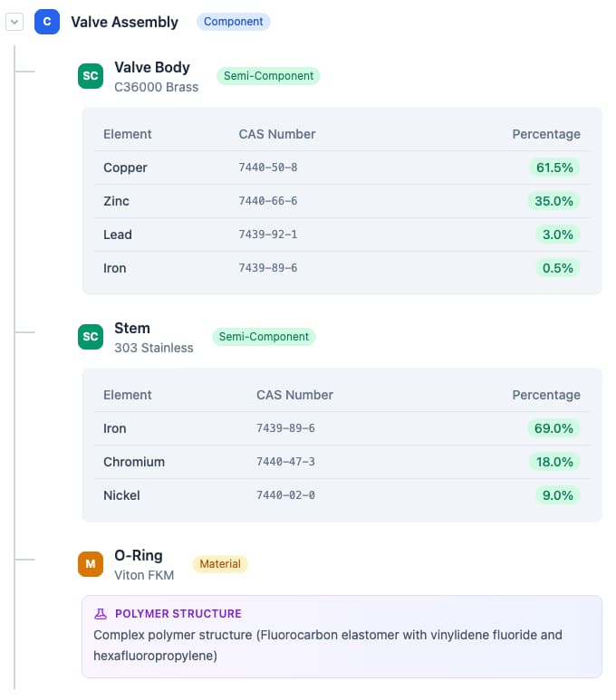
Step 3: Create Component Structure
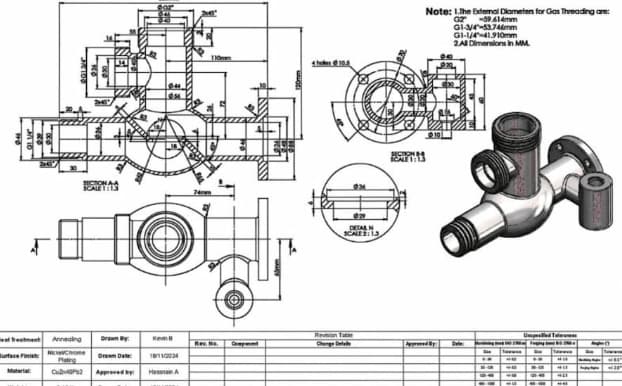
Example: Brass Valve Assembly
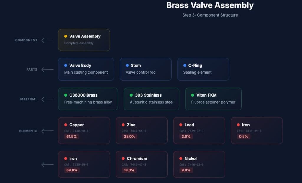
Step 4: Classify and Code
IMDS uses standardized classification codes:
| Code Range | Category |
|---|---|
| 1.x | Steel and iron materials |
| 2.x | Light alloys, cast and wrought alloys |
| 3.x | Heavy metals, cast and wrought alloys |
| 4.x | Special metals |
| 5.x | Polymer materials |
| 6.x | Process polymers |
| 7.x | Other materials and material compounds |
| 8.x | Electronics / electrics |
| 9.x | Fuels and auxiliary means |
Step 5: Validate and Submit
IMDS checks include:
- Weight balance (components sum to parent weight)
- Prohibited substance screening
- Missing information flags
- Customer-specific validation rules
Common IMDS Errors and Solutions
| Error | Cause | Solution |
| Weight mismatch | Components don’t sum to parent | Recalculate and correct weights |
| Jokers | Unknown substances as placeholders | Replace with actual substances or analysis |
| Missing CAS | Substance without CAS number | Look up in IMDS substance list |
| Rejected substance | Banned or restricted material | Find alternative material |
| Application code error | Wrong location classification | Verify against IMDS code list |

Integrating IMDS into Quality Systems
Process Integration Points
1. New Product Introduction (NPI)
- IMDS required before PPAP approval
- Include in APQP timing plan
- Assign IMDS responsibility in project team
2. Supplier Management
- Require IMDS capability in supplier selection
- Include IMDS data in supplier quality agreements
- Audit supplier IMDS processes
3. Engineering Change Control
- Any material change requires IMDS update
- Change board must review IMDS implications
- Customer notification for significant changes
4. Production
- Material lot traceability connects to IMDS
- Ensure actual materials match IMDS declaration
- Control substitution risks
Documentation Control
Required Records
- All submitted MDS IDs and versions
- Supporting material certifications
- Supplier MDS references
- Customer acceptance confirmations
- Change history
Retention Requirements
- Production life + 15 years (automotive typical)
- Verify specific customer requirements
- Some OEMs require 30+ years
Southeast Asia Implementation
Regional Challenges
Supplier Base Limitations
- Many Tier 2/3 suppliers unfamiliar with IMDS
- Limited access to testing for substance verification
- Language barriers in system navigation
Solutions
- Provide IMDS training to key suppliers
- Offer template MDSs for common materials
- Engage IMDS service providers for support
- Consider English-Chinese-Thai system translations
Local Regulatory Considerations
Thailand Automotive Standards
- TISI (Thai Industrial Standards Institute) alignment with international standards
- Board of Investment (BOI) incentives for EV supply chain participation
- Increasing IMDS requirements from Japanese OEMs with Thai operations
ASEAN Integration
- ASEAN Automotive Federation harmonization efforts
- Cross-border data sharing challenges
- Mutual recognition of certifications developing
Working with Regional OEMs
| OEM | IMDS Requirements | Special Considerations |
| Toyota (Thailand) | Full IMDS required | Japanese material standards |
| Honda (Thailand) | Full IMDS required | Strict change control |
| Ford (Thailand) | Full IMDS required | Aligned with global Ford |
| MG/SAIC (Thailand) | Growing IMDS adoption | Chinese material databases |
| Local Assemblers | Varies | Often less stringent |
Best Practices for Material Documentation
1. Supplier Qualification
Before approving material suppliers:
- Verify certification capability
- Review sample MTRs for completeness
- Confirm IMDS experience (for automotive)
- Audit traceability systems
2. Incoming Inspection
For each material lot:
- Compare MTR to specification
- Verify marking matches paperwork
- Check for certificate authenticity
- Retain samples if required
3. Material Traceability
Maintain lot tracking:
- Heat/lot number linked to finished parts
- First-in-first-out (FIFO) stock rotation
- Segregation of different lots
- Computerized tracking systems preferred
4. Customer Communication
Proactive documentation sharing:
- Provide certifications with shipments
- Maintain customer portals for document access
- Notify of any certificate delays
- Offer pre-submission review for critical parts
Conclusion
In today’s documentation-driven manufacturing environment, mastering material certifications and IMDS integration is no longer optional, it is a critical requirement for maintaining compliance, ensuring traceability, and securing long-term customer trust. From validating mill test reports to building accurate IMDS submissions, suppliers that implement structured, repeatable documentation processes position themselves as reliable partners within global supply chains.
For companies operating in highly competitive sectors such as automotive and industrial manufacturing, this level of discipline becomes even more important when supporting processes like forging in Vietnam, where international buyers increasingly expect full transparency, material traceability, and regulatory alignment. By combining strong documentation practices with robust manufacturing capabilities, suppliers can not only meet compliance standards but also unlock greater market access and long-term growth opportunities.
FAQ
Q1: How long must we retain material certifications?
A: Retention periods vary by industry:
- Automotive (IATF 16949): Production life + 1 year (minimum)
- Aerospace (AS9100): 40 years from shipment
- Medical (ISO 13485): Device lifetime + 2 years (often 10-15+ years)
- General Industrial: Typically 7-10 years
Always verify specific customer requirements, which may exceed industry standards.
Q2: Can we use “typical” values from MTRs instead of testing each lot?
A: Generally no for critical applications:
- “Typical” or “nominal” values don’t represent actual lot
- Most automotive and aerospace requires actual test results
- Some non-critical applications may accept typical values with customer approval
- When in doubt, require actual test results
Q3: What if our material supplier won’t provide IMDS data?
A: Options:
- Find alternative supplier with IMDS capability
- Create material yourself from composition data (requires accurate analysis)
- Use IMDS service provider to create entries
- Request customer assistance for critical sole-source materials
Note: Creating materials from scratch requires accurate substance analysis and estimates not acceptable.
Q4: Do we need IMDS for prototype parts?
A: Typically yes:
- Most OEMs require IMDS before PPAP approval
- Prototype phase IMDS often marked “for prototype only”
- Production IMDS must be updated for any material changes
- Early IMDS submission prevents production delays
Q5: How do we handle confidential material formulations?
A: IMDS provides protection mechanisms:
- Pseudo-substances: Hide exact formulation while declaring regulated substances
- Joker system: For complex polymers where exact formula confidential
- Supplier MDS: Reference supplier’s confidential MDS without disclosure
- OEM agreement: Some customers accept offline disclosure for highly confidential materials
Q6: What substances trigger IMDS reporting requirements?
A: Two thresholds:
- REACH SVHC: >0.1% by weight (reportable but not prohibited)
- GADSL: Declarable substances at specified thresholds
- ELV banned: Lead, mercury, cadmium, hexavalent chromium which is prohibited with limited exceptions
Q7: Can we update an IMDS entry after customer acceptance?
A: Yes, through versioning:
- New version supersedes old
- Customer must accept new version
- Always increment version for any change
- Maintain history of all versions
Q8: What’s the penalty for incorrect IMDS data?
A: Consequences can be severe:
- PPAP rejection: Cannot ship production parts
- Stop shipments: Existing business halted until corrected
- Fines: For regulatory non-compliance (REACH, ELV)
- Recall liability: If non-compliant products reach market
- Supplier score impact: Affects future business opportunities
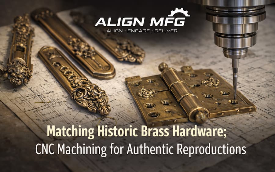
Matching Historic Brass Hardware: CNC Machining for Authentic Reproductions
What is CNC Machining?
CNC machining (Computer Numerical Control machining) is a precision manufacturing process where computer-controlled machines remove material from solid metal or plastic to create highly accurate parts based on digital designs. By following programmed toolpaths, CNC machines can replicate complex geometries, tight tolerances, and fine details with consistent repeatability. This makes CNC machining especially valuable for applications such as historic hardware reproduction, where matching the original dimensions, fit, and functionality is critical.
Introduction: When Authenticity Matters
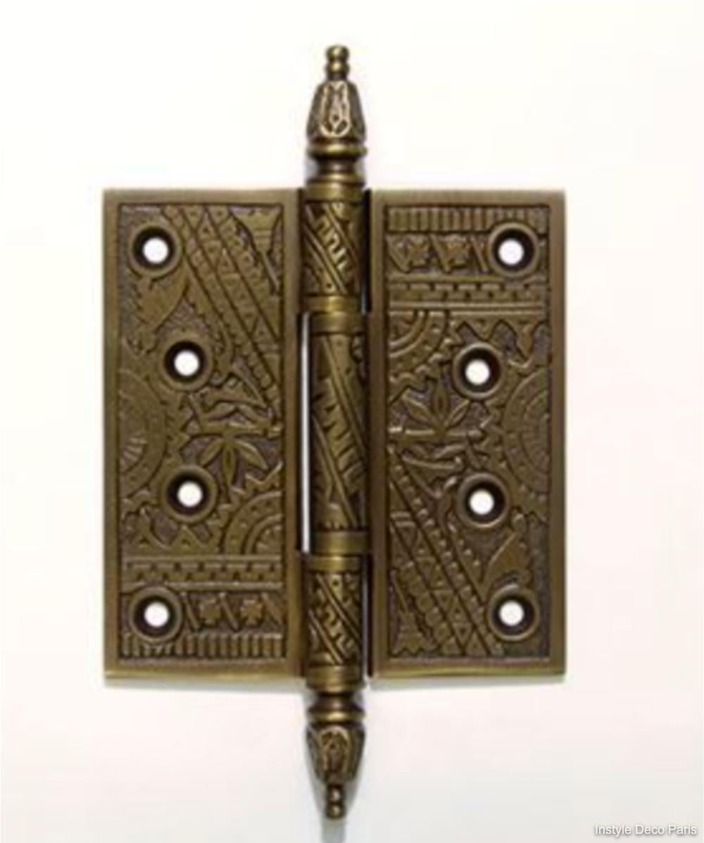
Historic brass hardware, ranging from ornate door handles on Victorian mansions to the simple yet elegant hinges of colonial homes, represents craftsmanship that modern mass production often fails to replicate. For restoration projects, heritage building maintenance, and authentic reproduction manufacturing, the challenge isn’t just creating something that looks similar; it’s achieving dimensional accuracy, material authenticity, and functional equivalence that satisfies preservation standards.
CNC machining has revolutionized historic hardware reproduction, enabling craftspeople and manufacturers to create pieces indistinguishable from originals while meeting modern performance requirements. This guide explores the intersection of historical accuracy and precision manufacturing.
The Heritage Hardware Market
Applications for Historic Reproductions
| Application Sector | Typical Components | Standards Requirements |
| Museum Restoration | Display cases, exhibit hardware | AAM guidelines, reversibility |
| Historic Homes | Door/window hardware, hinges | Secretary of Interior Standards |
| Government Buildings | Legislative chambers, courts | GSA guidelines, Buy American |
| Religious Buildings | Altar hardware, sanctuary fittings | Denominational preservation rules |
| Theater/Film | Set dressing, functional props | Authenticity for period accuracy |
| Luxury Residential | Custom homes seeking period style | Client aesthetic requirements |
| Educational Institutions | Campus heritage buildings | State preservation office standards |
Preservation Standards Overview
Secretary of Interior’s Standards for Rehabilitation
- Standard 2: Preserve historic character
- Standard 6: Repair rather than replace
- Standard 9: Distinguish new work from old (when replacement necessary)
National Park Service Guidelines
- Document existing conditions thoroughly
- Use physical and photographic analysis
- Match materials, design, and finish historically
- Minimum intervention approach
Analyzing Historic Hardware
Documentation and Measurement
Step 1: Photographic Documentation
- High-resolution images from multiple angles
- Macro photography of surface details and patina
- Scale reference in each image
- UV photography to reveal hidden markings
Step 2: Dimensional Analysis
| Measurement Tool | Precision | Application |
| Digital Calipers | ±0.001″ | General dimensions, thickness |
| Micrometers | ±0.0001″ | Precision features, shaft diameters |
| Height Gauges | ±0.001″ | Vertical features, step heights |
| Optical Comparators | ±0.0005″ | Complex profiles, contours |
| 3D Laser Scanners | ±0.002″ | Overall form, organic shapes |
| CT Scanning | ±0.001″ | Internal features, hidden geometry |

Step 3: Material Analysis
Non-Destructive Testing (Preferred)
- XRF (X-Ray Fluorescence): Identifies alloy composition
- Hardness Testing: Confirms temper and alloy type
- Ultrasonic Testing: Detects internal cracks or voids
Destructive Testing (When Sacrifice Acceptable)
- Spectrographic Analysis: Precise elemental composition
- Metallographic Examination: Grain structure, porosity
- Tensile Testing: Mechanical properties
Common Historic Brass Alloys
| Era | Typical Alloy | Characteristics | Modern Equivalent |
| Colonial (1600-1776) | C23000 (85/15) | Reddish color, soft, formable | C23000, C83600 |
| Federal (1776-1830) | C26000 (70/30) | Yellow color, harder | C26000 |
| Victorian (1837-1901) | C28000 (60/40) | Golden color, cast decorative | C28000, C83600 |
| Arts & Crafts (1880-1920) | C27000 (65/35) | Warm color, hand-forged look | C27000 |
| Art Deco (1920-1940) | C36000 (machined) | Bright finish, geometric forms | C36000 |
| Mid-Century (1945-1960) | Various | Often plated, modern alloys | Match original XRF |
CAD Modeling for Historic Hardware
Capturing Organic Forms
Historic hardware often features hand-finished details that don’t translate directly to CAD:
Challenges
- Irregular surfaces from sand casting
- Tool marks from hand finishing
- Worn surfaces from use
- Intentional asymmetry in hand-crafted pieces
Solutions
| Approach | Method | Best For |
| NURBS Surfacing | Control point manipulation | Flowing, organic shapes |
| Sub-D Modeling | Subdivision surfaces | Sculptural, free-form details |
| Reverse Engineering | Scan-to-CAD | Exact reproduction of complex forms |
| Parametric Features | Constraint-based modeling | Geometric, machined components |
| Hybrid Approach | Combine methods | Complex assemblies |
Tolerancing for Function
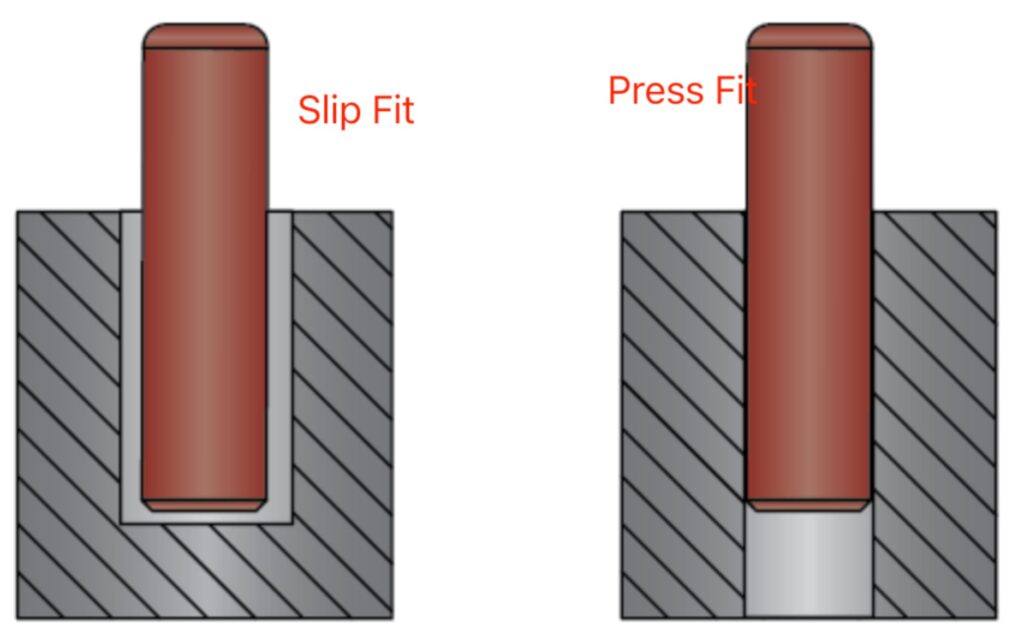
Fit Considerations
| Interface Type | Recommended Tolerance | Notes |
| Pivot/Pin Clearance | +0.002″ to +0.005″ | Allows smooth operation |
| Sliding Fit | +0.001″ to +0.003″ | Smooth, controlled motion |
| Press Fit | -0.001″ to -0.003″ | Permanent assembly |
| Thread Engagement | Class 2B (standard) | General hardware |
| Thread Engagement | Class 3B (precision) | Fine adjustment hardware |
| Backplate Seating | ±0.005″ | Cosmetic only |
Accounting for Patina Buildup Original hardware may have operated with significant patina accumulation. Reproductions should:
- Provide slight additional clearance at wear points
- Specify break-in period in documentation
- Use compatible lubricants (not modern synthetics that alter patina)
CNC Machining Strategies
Workholding Considerations
Historic hardware often features:
- Thin, delicate sections
- Complex external geometry
- Critical surface finishes
- No flat reference surfaces
Specialized Fixturing
| Component Type | Fixturing Approach |
| Ornate Backplates | Vacuum chuck with custom gasket |
| Curved Handles | Soft-jaw vise with matching contour |
| Delicate Spindles | Collet chuck with minimal clamping |
| Asymmetric Forms | 5-axis positioning with tailstock support |
| Thin Sections | Wax mounting or freeze-fit tooling |
Toolpath Strategies
Roughing
- High-efficiency milling (HEM) for material removal
- Leave 0.010-0.020″ stock for finishing
- Avoid heat buildup that affects temper
Semi-Finishing
- Ball mill passes to prepare for final form
- Maintain consistent stepover for surface quality
- 0.005″ stock remaining
Finishing
| Feature Type | Tool | Strategy |
| Flat Surfaces | Face mill or end mill | Climb milling, fine stepover |
| Contours | Ball end mill | Constant scallop height |
| Sharp Corners | Corner radius or pencil mill | Multiple passes |
| Fine Details | Tapered ball mill | High-speed machining |
| Text/Engraving | Engraving cutter or V-bit | Single pass at full depth |
Surface Finish Considerations
Achieving Period-Appropriate Finishes
| Era/Style | Target Finish | CNC Approach | Post-Process |
| Early Hand-Forged | Hammer marks, irregular | Intentional toolpath variation | Hand distressing |
| Victorian Cast | As-cast texture | Rough pass only, no finish cut | Chemical patina |
| Industrial Era | Machined but not polished | Standard finishing passes | Brushed finish |
| Art Deco | High polish, geometric | Fine finishing, minimal scallops | Polishing, lacquer |
| Arts & Crafts | Hand-rubbed appearance | Directional tool marks preserved | Oil finish |
Tool Marks as Features Some reproductions benefit from visible tool marks that suggest hand crafting:
- Program intentional scallop patterns
- Use larger stepovers in visible areas
- Preserve witness marks from setups
Material Selection for Authenticity
Color Matching
Brass color varies by alloy and finish. Spectrophotometer analysis of originals:
| Alloy | L* (Lightness) | a* (Red-Green) | b* (Yellow-Blue) |
| C23000 | 68-72 | +8 to +12 | +28 to +32 |
| C26000 | 70-74 | +6 to +10 | +32 to +36 |
| C27000 | 72-76 | +4 to +8 | +34 to +38 |
| C28000 | 74-78 | +2 to +6 | +36 to +40 |
Target reproduction finish should match original Lab values within ±2 units
Mechanical Properties
Matching Strength and Work Hardening
Historic hardware may have work-hardened areas from forming:
| Temper | Tensile Strength | Hardness | Application |
| Annealed (O) | 40,000 PSI | 55 HRB | Deep forming, soft details |
| Quarter Hard (H01) | 50,000 PSI | 65 HRB | Moderate forming |
| Half Hard (H02) | 60,000 PSI | 75 HRB | Springs, latches |
| Hard (H04) | 70,000 PSI | 85 HRB | Rigid components |
| Extra Hard (H08) | 80,000 PSI | 95 HRB | Maximum strength |
Historical Accuracy vs. Modern Requirements
Lead Content Considerations
- Pre-2014 hardware: May contain 4-8% lead
- Modern reproductions: Must comply with NSF/ANSI 372 (<0.25% lead)
- Solution: Use silicon brass (C69300) or bismuth brass for machinability
Surface Coatings
- Original: May have mercury gilding, lacquer, or natural patina
- Modern: Lacquer, wax, or controlled patina
- Match appearance while ensuring durability
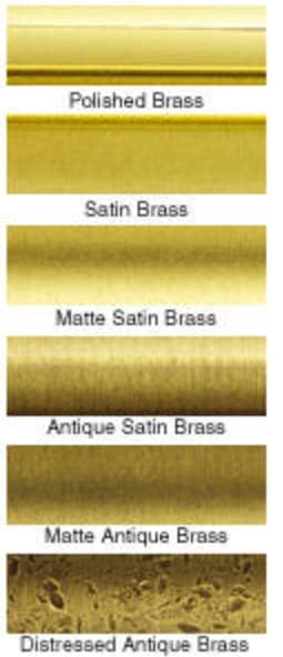
Finishing and Patination
Mechanical Finishes
| Finish Type | Process | Appearance |
| Brushed | 220-400 grit directional sanding | Subtle lines, matte |
| Satin | Non-woven abrasive, random orbit | Soft sheen, no direction |
| Bright | Polishing to mirror | High reflectivity |
| Antique | Selective darkening, highlight removal | Aged appearance |
| Oil-Rubbed | Dark base with bronze highlights | Deep, rich tones |
Chemical Patination
Traditional Formulas (Use with Safety Precautions)
| Patina Type | Formula | Application |
| Brown/Antique | Ferric nitrate solution | Even application, neutralize |
| Green/Verdigris | Ammonium chloride + copper sulfate | Controlled exposure |
| Black | Liver of sulfur (potassium sulfide) | Dip or brush, seal immediately |
| Red/Orange | Heat + salt solution | Torch coloring |
Modern Equivalents
- Commercial patina solutions (JAX, Birchwood-Casey)
- More consistent, safer handling
- Better documentation for reproducibility
Protective Coatings
| Coating | Durability | Reversibility | Best For |
| Microcrystalline Wax | Moderate | Excellent | Museum pieces, low-use |
| Incralac | Good | Good | Exterior, moderate exposure |
| Clear Powder Coat | Excellent | Poor | High-traffic, functional |
| Lacquer | Fair | Fair | Interior, decorative |
| None (Living Finish) | N/A | N/A | High-use, intentional aging |
Quality Control for Reproductions
Dimensional Verification
First Article Inspection
- CMM measurement of all critical dimensions
- Surface finish measurement (Ra, Rz)
- Comparison to original artifact or CAD model
- Documentation package for client approval
Statistical Process Control
- Key characteristics monitored in production
- Control charts for critical dimensions
- Go/no-go gauges for rapid inspection
Functional Testing
| Test | Method | Acceptance Criteria |
| Cycle Testing | Automated open/lose cycles | 50,000 cycles minimum |
| Load Testing | Static load application | 3× working load |
| Salt Spray | ASTM B117 | Per specification |
| Hardness | Rockwell or Brinell | Within alloy specification |
| Color Match | Spectrophotometer | ΔE <2.0 from standard |
Documentation Package
Comprehensive reproduction records should include:
- Photographs of original artifact
- Dimensional measurement report
- Material certification
- Finishing process documentation
- Patina formulation
- Care and maintenance instructions
- Certificate of authenticity
Southeast Asia Heritage Projects
Regional Architectural Heritage
Thailand
- Traditional Thai architecture: Ornate gilded hardware
- Colonial influence: Sino-Portuguese mixed styles
- Royal projects: Strict authenticity requirements
Colonial Southeast Asia
- Dutch, British, French architectural hardware
- Mixed cultural influences
- Tropical climate considerations
Sourcing Considerations
Local Material Availability
- Brass rod and bar readily available in Bangkok industrial areas
- Lead-free alloys increasingly available
- Specialty alloys may require import
Export Considerations
- CITES documentation if hardware contains ivory or other restricted materials
- Cultural property clearance for certain antiquities
- Country of origin marking requirements
Conclusion
Reproducing historic brass hardware requires more than visual similarity—it demands precision, material authenticity, and a deep understanding of both traditional craftsmanship and modern manufacturing techniques. CNC machining bridges this gap by enabling accurate replication of complex geometries, controlled tolerances, and consistent surface finishes while maintaining the functional integrity of the original components.
From detailed measurement and material analysis to advanced CAD modeling and finishing processes, each step plays a critical role in achieving results that meet both preservation standards and modern performance requirements. When executed correctly, CNC machining allows manufacturers to deliver components that are visually and functionally aligned with historic originals.
At Align Manufacturing, we specialize in precision-driven reproduction projects, combining engineering expertise with disciplined process control to ensure consistent, high-quality outcomes. With growing capabilities for machining in Vietnam, we are able to support both low-volume custom work and scalable production, offering our partners a reliable solution for complex and detail-sensitive components.
Ultimately, successful historic hardware reproduction is not just about making parts—it’s about preserving craftsmanship, ensuring performance, and delivering long-term value through the right manufacturing strategy.
FAQ
Q1: How accurate should reproduction brass hardware be to the original?
A: Accuracy requirements depend on application:
- Museum display: Exact to 0.001″ where visible
- Functional restoration: Within tolerance for operation
- General reproduction: Visually indistinguishable at 3 feet
- Inspired-by pieces: Captures character, not exact copy
Always document deviations from original when they occur.
Q2: Can we improve the original design of brass hardware while maintaining authenticity?
A: Under Secretary of Interior Standards, improvements must be:
- Reversible without damage to historic fabric
- Distinguishable from original work
- Documented thoroughly
- Approved by appropriate authorities
Common acceptable improvements: Hidden bearings, modern lubricants, stainless steel pins in brass housings.
Q3: What’s the minimum order quantity for custom brass reproduction hardware?
A: CNC machining enables economical small quantities:
- Prototype/single piece: ₫12,250,000–₫49,000,000+ ($500–$2,000+) (high setup cost)
- Small batch (10–50): ₫1,225,000–₫4,900,000 per piece ($50–$200 per piece)
- Medium batch (50–200): ₫735,000–₫2,450,000 per piece ($30–$100 per piece)
- Full production (200+): ₫367,500–₫1,225,000 per piece ($15–$50 per piece)
Costs highly dependent on complexity and finishing requirements.
Q4: How do we handle brass hardware with maker’s marks or logos?
A: Several approaches:
- Exact reproduction: Requires permission from trademark holder
- Generic replacement: Omit marks, reproduce form only
- Documentation: Photograph and preserve original marks separately
- Period-appropriate mark: Use shop mark in period style
When in doubt, consult with a preservation officer or legal counsel.
Q5: Can worn original brass hardware be restored instead of replaced?
A: Restoration is always preferred over replacement when feasible:
- Metal consolidation for deteriorated castings
- Weld repair of cracks or breaks
- Replating worn surfaces
- Replication of missing components only
Restoration requires specialized conservators; CNC machining typically for replacement when restoration is not viable.
Q6: What file formats are needed for CNC machining historic brass hardware?
A: Preferred formats:
- STEP (.stp): Universal CAD exchange
- IGES (.igs): Surface data, older systems
- STL: For 3D printing patterns for casting
- Native CAD: SolidWorks, Fusion 360, etc.
Include:
- 3D solid model
- 2D drawings with tolerances
- Surface finish specifications
- Material callouts
Q7: How do we match the weight/heft of original brass hardware?
A: Weight is a critical authenticity factor:
- Use correct alloy density (brass: 0.308 lb/cu in)
- Match wall thickness exactly
- Account for any hollow sections
- Specify weight tolerance (typically ±5%)
If the original has lead weights (common in sash hardware), replicate with hidden steel or brass to avoid lead content issues.
Q8: What’s the lead time for custom reproduction brass hardware?
A: Typical timeline:
- Documentation/measurement: 1-2 weeks
- CAD modeling: 1-3 weeks
- First article production: 2-4 weeks
- Client approval/revisions: 1-2 weeks
- Production: 2-6 weeks (quantity dependent)
- Finishing/patination: 1-2 weeks
Total: 8-16 weeks typical
Rush service available at premium (30-50% upcharge) for urgent restoration projects.
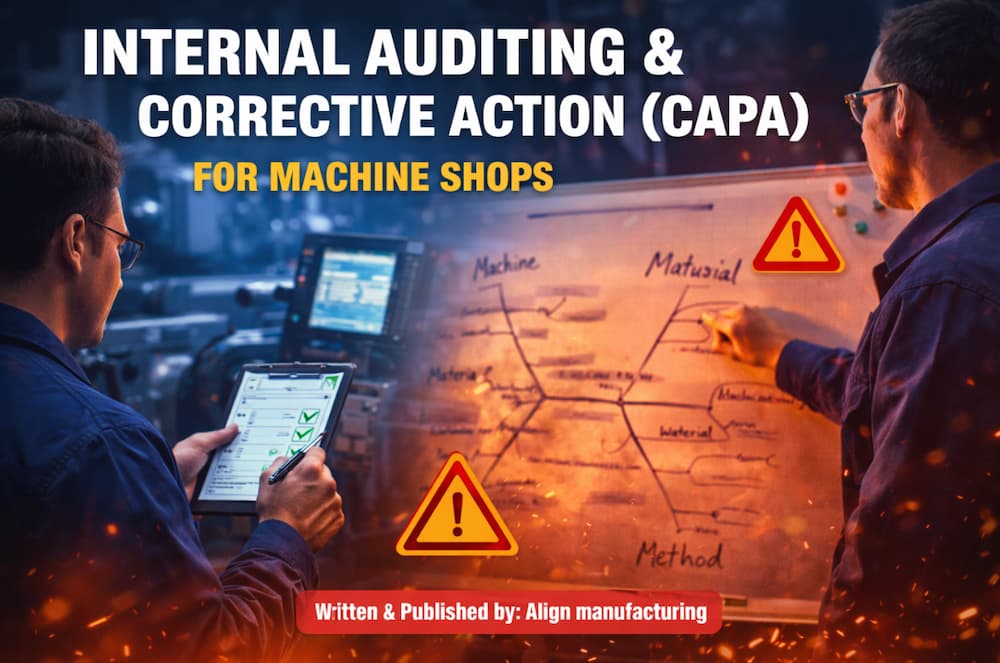
Internal Auditing and Corrective Action (CAPA) for Machine Shops
Introduction: Building a Quality-First Culture
In the precision-driven world of CNC machining and manufacturing, quality isn’t an inspection step, it’s a continuous process woven throughout operations. Internal auditing and Corrective and Preventive Action (CAPA) form the backbone of proactive quality management, enabling machine shops to identify issues before they reach customers, systematically address root causes, and prevent recurrence.
This comprehensive guide provides machine shop managers, quality engineers, and operators with actionable frameworks for implementing effective internal audit programs and CAPA systems that drive continuous improvement while meeting ISO 9001, IATF 16949, and AS9100 requirements.
Understanding Internal Auditing in Manufacturing
What is an Internal Audit?
An internal audit is a systematic, independent examination of a manufacturing organization’s quality management system (QMS) to determine whether quality activities and related results comply with planned arrangements. Unlike external audits conducted by customers or certification bodies, internal audits are self-directed evaluations designed to drive improvement.
Types of Internal Audits for Machine Shops
| Audit Type | Frequency | Focus Area | Personnel Required |
| System Audits | Annual | Entire QMS against ISO/AS standards | Certified internal auditor |
| Process Audits | Quarterly | Specific manufacturing processes | Process engineer + QA |
| Product Audits | Monthly | Finished parts against specifications | Quality inspector |
| Layered Process Audits (LPA) | Daily/Weekly | Critical control points | Production supervisor |
| Supplier Audits | Annually | Subcontractor capabilities | Purchasing + QA |
| 5S Audits | Weekly | Workplace organization | Production team |
Internal Audit Program Structure
Annual Audit Schedule Example
| Month | Audit Focus | Standard Clause | Auditor |
| January | Management processes | ISO 9001: 4-5 | Quality Manager |
| February | Resource management | ISO 9001: 7 | HR + Operations |
| March | Product realization – Planning | ISO 9001: 8.1 | Engineering |
| April | Purchasing and supplier control | ISO 9001: 8.4 | Purchasing |
| May | Production and service provision | ISO 9001: 8.5 | Production Mgr |
| June | Monitoring and measurement | ISO 9001: 9 | QA Manager |
| July | Corrective action processes | ISO 9001: 10.2 | Quality Manager |
| August | Document and record control | ISO 9001: 7.5 | Document Control |
| September | Calibration and inspection | ISO 9001: 7.1.5 | Metrology Lead |
| October | Customer-related processes | ISO 9001: 8.2 | Sales + QA |
| November | Internal audit process | ISO 9001: 9.2 | Management Rep |
| December | Management review preparation | ISO 9001: 9.3 | Top Management |

Planning Effective Internal Audits
Pre-Audit Preparation
1. Define Audit Scope and Criteria
- Identify processes to be audited
- Reference applicable standards (ISO 9001, IATF 16949, AS9100)
- Review previous audit findings
- Consider customer-specific requirements
2. Select and Prepare the Audit Team
- Auditors must be independent of audited activities
- Minimum requirement: One lead auditor with formal training
- Larger audits: Audit team with defined roles
- Southeast Asia consideration: Ensure language proficiency
3. Develop Audit Checklists
Sample Process Audit Checklist: CNC Turning Operation
| Checkpoint | Evidence Required | Finding | Notes |
| Work instruction available at station? | Posted/current revision | ☐ C ☐ NC ☐ O | |
| Operator trained and certified? | Training records, skill matrix | ☐ C ☐ NC ☐ O | |
| First piece inspection completed? | FAI report, sign-off | ☐ C ☐ NC ☐ O | |
| In-process inspection per control plan? | Inspection records | ☐ C ☐ NC ☐ O | |
| Statistical process control active? | SPC charts, capability data | ☐ C ☐ NC ☐ O | |
| Tooling identified and within life? | Tool life tracking | ☐ C ☐ NC ☐ O | |
| Machine calibration current? | Calibration stickers, certs | ☐ C ☐ NC ☐ O | |
| Preventive maintenance on schedule? | PM records, work orders | ☐ C ☐ NC ☐ O | |
| Nonconforming material identified? | Red tags, quarantine area | ☐ C ☐ NC ☐ O | |
| Corrective actions from previous audits closed? | CAR tracking | ☐ C ☐ NC ☐ O |
C = Conforming, NC = Non-Conforming, O = Observation
Conducting the Audit
Opening Meeting (15-30 minutes)
- Introduce audit team
- Confirm scope and schedule
- Explain audit methodology
- Address confidentiality
On-Site Audit Activities
- Interview Personnel: Ask open-ended questions
- “Walk me through how you set up this job”
- “How do you know when a tool needs changing?”
- “What do you do if you find a defect?”
- Observe Operations: Watch actual work being performed
- Compare to documented procedures
- Note deviations and best practices
- Photograph (with permission) for evidence
- Review Records: Examine objective evidence
- Inspection records, SPC charts
- Training records, certifications
- Maintenance logs, calibration certificates
- Previous audit findings and closures
Closing Meeting (30-45 minutes)
- Present findings (non-conformities and observations)
- Allow auditee to respond and clarify
- Discuss timeline for corrective actions
- Issue draft report within 3-5 business days
Writing Non-Conformity Reports
Non-Conformity Structure (CAR Format)
1. Statement of Non-Conformity Clear, factual description of what was found:
“The CNC milling work instruction WI-045 Rev C specifies measurement of hole diameter at position A after operation OP-20. Review of inspection records for Job #23456 (run date 15 March 2026) showed no diameter measurement recorded, and the operator confirmed this dimension is not routinely checked.”
2. Reference to Standard/Requirement
“This constitutes a non-conformity with ISO 9001:2015 Clause 8.5.1 (c) – ‘the implementation of monitoring and measurement activities at appropriate stages to verify that criteria for control of processes…have been met.'”
3. Classification
- Major: Systemic failure, multiple minor NCs on same clause, potential customer impact
- Minor: Isolated incident, limited impact, easily correctable
4. Evidence References
- Document numbers, revision levels
- Photographs (if applicable)
- Interview notes
- Record samples with dates
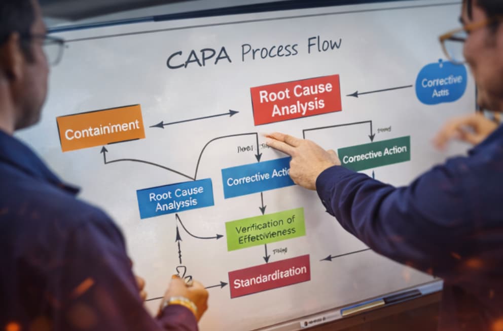
The CAPA Process: From Finding to Fix
CAPA vs. Correction
| Aspect | Correction | Corrective Action | Preventive Action |
| Timing | Immediate | Short-term | Long-term |
| Focus | Symptom | Root cause | Potential issues |
| Goal | Fix the problem | Prevent recurrence | Prevent occurrence |
| Example | Rework nonconforming part | Fix broken fixture | Update PM schedule |
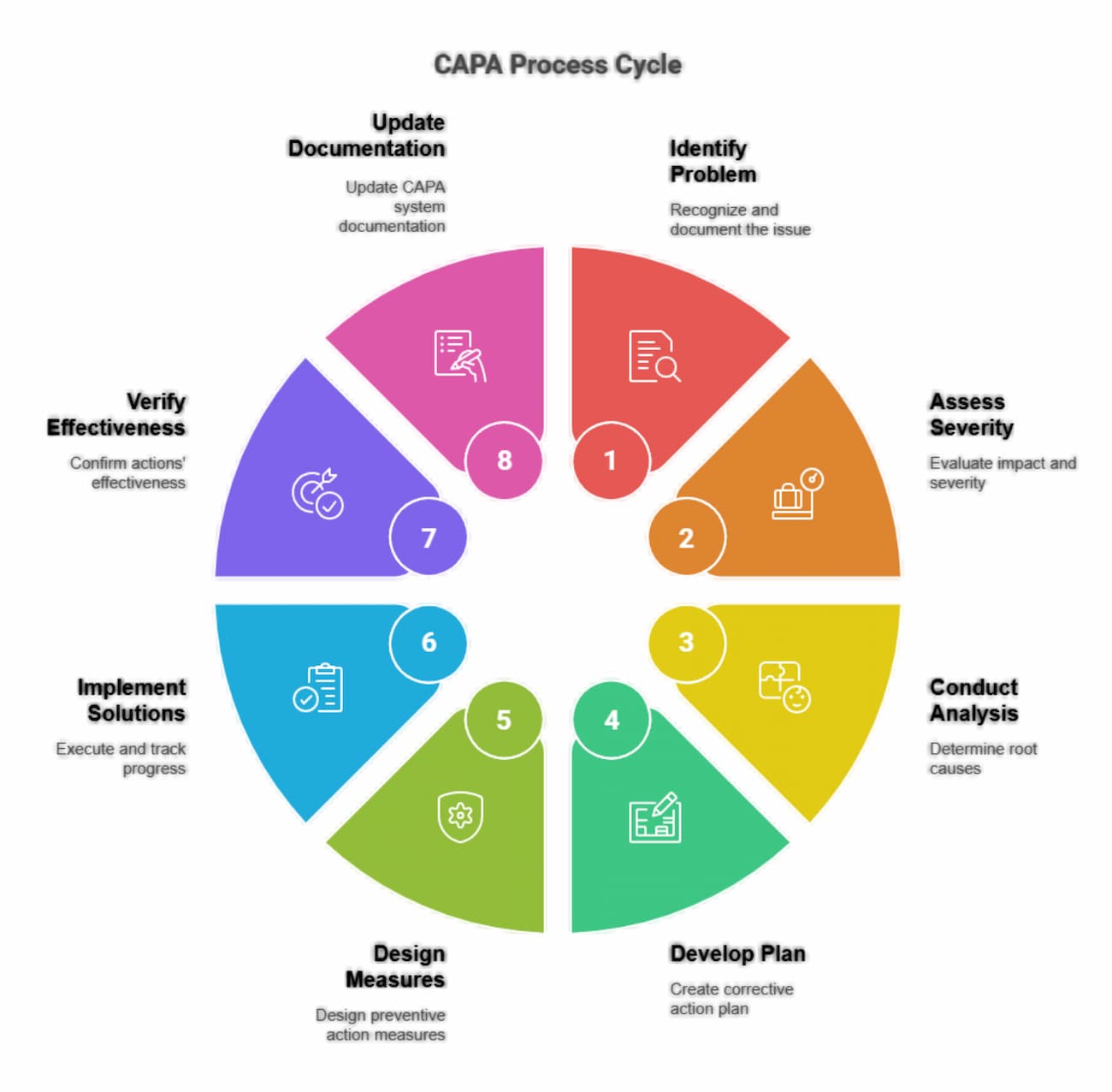
The 8D Problem-Solving Method
Originally developed by Ford Motor Company, 8D is widely used in manufacturing:
D0: Plan
- Define the problem symptom
- Establish emergency response action if needed
- Form the team
D1: Establish the Team
- 4-6 members with process knowledge
- Include operator, engineer, quality representative
- Assign roles: Champion, Team Leader, Recorder, Members
D2: Describe the Problem Use the 5W2H framework:
- What is the problem? (defect type, characteristic)
- Where was it found? (location, machine, shift)
- When did it occur? (date, time, sequence)
- Who is affected? (customer, process, product)
- Why is it a problem? (impact, severity)
- How was it detected? (inspection method, frequency)
- How many were affected? (quantity, percentage)
D3: Develop Interim Containment
- Stop the bleeding: quarantine suspect material
- Sort good from bad
- Implement 100% inspection if necessary
- Document containment effectiveness
D4: Root Cause Analysis Investigate both:
- Escape Point: Why did the defect reach the customer?
- Root Cause: Why did the defect occur?
Use multiple tools:
- 5 Whys: Ask “why” five times to drill down
- Fishbone (Ishikawa): Categories – Man, Machine, Material, Method, Measurement, Environment, Management
- Fault Tree Analysis: Top-down logic analysis
- FMEA: Review for overlooked failure modes
D5: Choose Permanent Corrective Actions
- Address root causes, not symptoms
- Verify actions don’t create new problems
- Define implementation timeline
- Assign responsibility
D6: Implement and Verify
- Execute corrective actions
- Train affected personnel
- Update documents (procedures, work instructions)
- Verify effectiveness with data (30-90 days minimum)
D7: Prevent Recurrence
- Apply lessons learned to similar processes
- Update FMEAs, Control Plans
- Revise training materials
- Communicate across organization
D8: Recognize the Team
- Document and share success
- Reward team members
- Archive for future reference
Root Cause Analysis Tools
The 5 Whys Technique
Example: Dimensional variation on turned parts
| Level | Question | Answer |
| 1 | Why are parts out of tolerance? | Because the cutting tool wears inconsistently |
| 2 | Why does the tool wear inconsistently? | Because feed rates vary between operators |
| 3 | Why do feed rates vary? | Because the parameter sheet is not at the machine |
| 4 | Why isn’t the parameter sheet at the machine? | Because the document control update hasn’t been distributed |
| 5 | Why hasn’t it been distributed? | Because the document change process has no verification step |
Root Cause: Document change process lacks verification of distribution.
| Category | Cause 1 | Cause 2 | Cause 3 |
|---|---|---|---|
| Man | Training | Fatigue | New hire |
| Machine | PM due | Vibration | Spindle |
| Material | Lot var | Mixed | Moisture |
| Method | WI not current | Shortcut | Method var |
| Measurement | Cal due | Gage worn | Method var |
Pareto Analysis
Rank defects by frequency to focus efforts:
| Defect Type | Count | Cumulative % |
| Dimensional | 45 | 45% |
| Surface finish | 30 | 75% |
| Burr | 12 | 87% |
| Contamination | 8 | 95% |
| Other | 5 | 100% |
Focus CAPA efforts on dimensional and surface finish issues first (75% of problems).
CAPA Documentation and Tracking
CAPA Record Requirements
Each CAPA must contain:
- Unique identifier (e.g., CAR-2026-047)
- Date opened and originator
- Problem description (linked to audit finding or NCR)
- Immediate containment actions and dates
- Root cause analysis documentation
- Corrective actions with assigned owners and due dates
- Implementation verification evidence
- Effectiveness verification with metrics
- Closure approval by quality management
- Dates for each milestone
CAPA Tracking Metrics
| Metric | Target | Calculation |
| Open CARs | <10 | Count of active CARs |
| Average age | <30 days | Sum of open days / total CARs |
| On-time closure | >95% | Closed on time / total closed |
| Effectiveness rate | >90% | Effective verifications / total closed |
| Recurrence rate | <5% | Repeated issues / total closed |
Southeast Asia Implementation Considerations
Cultural Factors
Challenge: Saving Face
- Non-conformities may be perceived as personal criticism
- Root cause analysis may avoid identifying human error
Solutions:
- Frame audits as “process reviews,” not “personnel evaluations”
- Use “we” language: “How can we improve this process?”
- Recognize that honest reporting of problems is encouraged
- Separate the person from the process in all documentation
Challenge: Hierarchical Communication
- Operators may not feel empowered to report issues to auditors
- Corrective actions may need management approval before implementation
Solutions:
- Include supervisors in audit closing meetings
- Establish clear escalation paths
- Empower team-level problem solving within defined limits
- Train management on the importance of rapid response
Language and Documentation
- Provide audit checklists in local language
- Use visual aids (photos, diagrams) to supplement written reports
- Consider bilingual auditors for international customers
- Ensure all personnel understand key quality terms
Regulatory Environment
Thailand Industrial Standards
- TISI (Thai Industrial Standards Institute) requirements for certain products
- Factory Act compliance for safety-related CAPAs
ASEAN Manufacturing Standards
- Harmonizing quality approaches across regional facilities
- Mutual recognition of supplier audits within ASEAN
Audit and CAPA Checklists
Pre-Audit Checklist
☐ Audit scope defined and documented
☐ Audit criteria identified (standards, procedures)
☐ Audit team selected and available
☐ Auditee notified with adequate lead time (1-2 weeks)
☐ Previous audit reports reviewed
☐ Customer complaints and CARs reviewed
☐ Checklists prepared
☐ Opening meeting scheduled
CAPA Implementation Checklist
☐ Root cause verified (not just symptom)
☐ Actions address root cause
☐ Containment verified effective
☐ Documents updated (procedures, WIs, drawings)
☐ Training completed and recorded
☐ Implementation verified within timeframe
☐ Effectiveness metrics defined
☐ Effectiveness verified with data
☐ No negative side effects introduced
☐ Lessons learned communicated
☐ Management approval for closure
FAQ
Q1: How often should we conduct internal audits?
A: ISO 9001 requires audits at planned intervals, typically interpreted as annual coverage of all processes. Best practice for machine shops:
- Entire QMS: Audited at least annually
- Critical processes: Semi-annually or quarterly
- Problem areas: Monthly until stable
- Layered Process Audits: Weekly for high-risk operations
Q2: Can the same person audit a process they work in?
A: No, auditors must be independent of the area being audited to ensure objectivity. However, they can audit other departments or processes. Small shops may need to bring in external auditors or cross-train employees to audit each other’s areas.
Q3: What’s the difference between a correction and a corrective action?
A: A correction fixes the immediate problem (rework a defective part). A corrective action fixes the root cause to prevent recurrence (repair the fixture that caused the defect). ISO 9001 requires corrective actions for non-conformities; corrections alone are insufficient.
Q4: How do we verify the effectiveness of corrective actions?
A: Effectiveness verification requires objective evidence that the problem has been eliminated:
- Statistical data showing defect reduction (minimum 30-90 days)
- No recurrence of the specific issue in subsequent production runs
- Process capability improvements
- Customer complaint reduction
- Audit findings showing sustained compliance
Q5: What if a corrective action doesn’t work?
A: Reopen the CAR and:
- Verify the root cause analysis was correct
- Investigate why the selected action failed
- Apply additional or different corrective actions
- Consider escalation to management for resource support
- Document lessons learned
Q6: How do we prioritize multiple audit findings?
A: Use risk-based prioritization:
- Safety issues: Immediate action required
- Customer impact: High priority, short timelines
- Systemic failures: Address before isolated issues
- Repeat findings: Escalate management attention
- Observations: Address as resources permit
Q7: Can we close a CAR before the effectiveness verification period is complete?
A: No, ISO 9001 requires evidence that corrective actions are effective. Closing before verification is complete violates the standard and risks recurrence. The only exception is if the CAR is reclassified as a preventive action with different timing requirements.
Q8: What’s the role of management review in audit and CAPA?
A: Management review (ISO 9001 Clause 9.3) must include:
- Status of actions from previous audits
- Results of internal and external audits
- Performance of external providers (supplier audits)
- Effectiveness of corrective actions
- Opportunities for improvement
- Resource needs for quality activities
Conclusion
Internal auditing and CAPA are not just compliance requirements, they are essential tools for building a resilient, quality-driven manufacturing operation. When implemented effectively, they transform audits from reactive exercises into proactive systems that continuously identify risks, eliminate root causes, and strengthen process control across the shop floor.
By establishing structured audit programs, clear non-conformity reporting, and disciplined CAPA workflows, machine shops can move beyond firefighting and toward sustainable improvement. The frameworks outlined in this guide, from audit planning and execution to root cause analysis and effectiveness verification, provide a practical roadmap for maintaining compliance while driving measurable operational gains.
For manufacturers operating in competitive regions such as Southeast Asia, the ability to demonstrate strong internal controls and consistent quality performance is a key differentiator. At Align Manufacturing, we support our partners by integrating robust audit and CAPA systems with production best practices, supplier management, and advanced manufacturing capabilities such as investment casting in Thailand, ensuring both process reliability and long-term scalability.
Ultimately, the goal is not just to pass audits, but to build a system where quality is embedded into every step of production which reduces risk, improves efficiency, and delivers consistent value to customers.
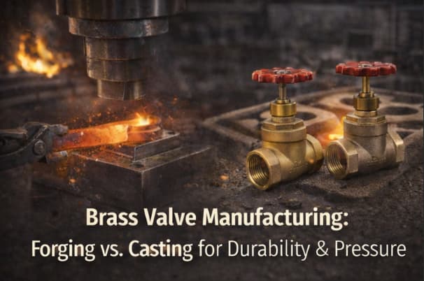
Brass Valve Manufacturing: Forging vs. Casting for Durability & Pressure
What Is Forging In Manufacturing?
Forging is a manufacturing process that shapes brass by applying compressive force to heated metal billets or bar stock. Under high pressure, the material is deformed into the desired valve shape, creating a dense structure with aligned grain flow. This results in superior mechanical strength, higher pressure resistance, and improved durability, making forging ideal for demanding and safety-critical applications.
What Is Casting In Manufacturing?
Casting is a manufacturing process where molten brass is poured into a mold and allowed to solidify into the desired shape. This method enables the production of complex geometries and internal passages that would be difficult or costly to machine or forge. While casting is more cost-effective and flexible in design, it typically produces components with lower mechanical strength compared to forged parts.
Introduction: The Critical Choice in Valve Production And Manufacturing
Brass valves are essential components in plumbing, industrial, and marine applications where reliable fluid control under pressure is non-negotiable. The debate between manufacturing methods of forging versus casting, fundamentally determines the valve’s mechanical properties, pressure ratings, durability, and cost. Understanding these differences enables buyers and engineers to make informed decisions that balance performance requirements with budget constraints.
This technical deep-dive compares forging and casting processes for brass valve manufacturing, examining how each method affects material structure, pressure handling, longevity, and economic considerations.
Understanding Manufactured Brass Valve Applications
Common Valve Types
| Valve Type | Primary Application | Pressure Requirements | Typical Manufacturing Method |
| Ball Valves | On/off flow control | 150-600 PSI WOG | Both forging and casting |
| Gate Valves | Isolation services | 125-250 PSI | Primarily casting |
| Globe Valves | Throttling applications | 150-300 PSI | Forging preferred |
| Check Valves | Backflow prevention | 200-600 PSI | Both methods |
| Pressure Relief Valves | Safety applications | 50-400 PSI set pressure | Forging required |
| Marine Valves | Seawater applications | 150-300 PSI | Forging with DZR brass |
Industry Manufacturing Standards
Brass valves must comply with multiple standards depending on application:
- ASTM B62: Standard specification for composition bronze or ounce metal castings
- ASTM B16/B16M: Free-cutting brass rod, bar and shapes for use in screw machines
- NSF/ANSI 61: Drinking water system components: health effects
- NSF/ANSI 372: Drinking water system components: lead content
- MSS SP-110: Ball valves threaded, socket-welding, solder joint, grooved and flared ends
- UL 252: Compressed gas pressure regulators
Forging: The Strength Advantage
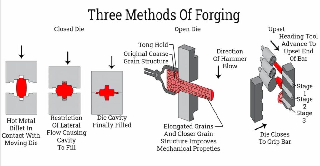
The Forging Process for Manufacturing Brass Valves
Forging shapes brass by applying compressive force to heated billets or bar stock. The process fundamentally transforms the material’s internal structure:
- Billet Preparation: Brass rod or bar (typically C36000 free-cutting brass or C37700 forging brass) is cut to weight
- Heating: Billets heated to 1,200-1,400°F (650-760°C) for optimal plasticity
- Forming: Mechanical presses (up to 2,500 tons) or hammers shape the heated brass into valve bodies
- Trimming: Excess material (flash) is removed
- Heat Treatment: Stress relief annealing for complex geometries
- Machining: Precision CNC finishing of seats, threads, and sealing surfaces
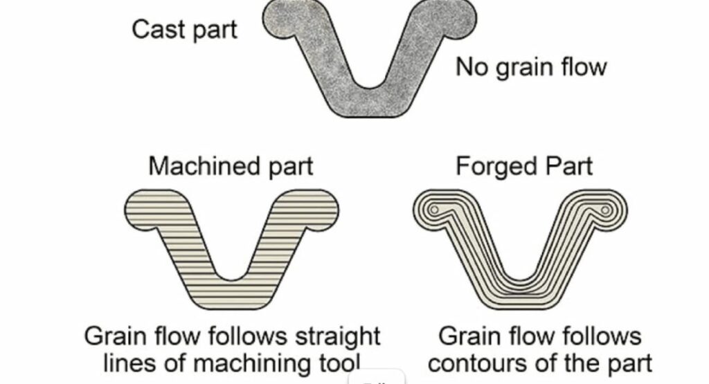
Metallurgical Benefits of Forging
Grain Structure Alignment Forging creates directional grain flow that follows the valve’s contours. This grain alignment provides:
- Superior fatigue resistance (3-5× better than castings)
- Higher impact strength
- Improved resistance to stress corrosion cracking
Porosity Elimination Unlike casting, forging eliminates internal porosity through compression:
- Zero gas porosity or shrinkage cavities
- Uniform density throughout the valve body
- Predictable pressure ratings without weak points
Mechanical Manufacturing Property Improvements
| Property | Forged Brass | Cast Brass | Improvement |
| Tensile Strength | 50,000-60,000 PSI | 30,000-40,000 PSI | +50-67% |
| Yield Strength | 35,000-45,000 PSI | 15,000-20,000 PSI | +100-125% |
| Elongation | 15-25% | 15-20% | Similar |
| Fatigue Strength | 18,000-22,000 PSI | 6,000-10,000 PSI | +120-200% |
| Hardness (Brinell) | 80-100 HB | 60-80 HB | +25-33% |
Pressure Rating Advantages In Manufacturing
Forged brass valves consistently achieve higher working pressure ratings:
- Standard Forged Valves: 600 PSI WOG (Water, Oil, Gas)
- High-Pressure Forged: 1,500+ PSI for hydraulic applications
- Steam Service: 250 PSI saturated steam ratings common
The absence of internal defects means forged valves can safely handle pressure spikes and thermal cycling that would risk casting failure.
When Forging is Essential In Manufacturing
Specify forged brass valves for:
- High-pressure applications (>300 PSI)
- Thermal cycling environments
- Safety-critical systems (gas, steam)
- Corrosive media (saltwater, chemicals)
- Applications requiring maximum longevity
- Aerospace and military specifications
Casting: The Economic and Geometric Advantage
Casting Processes for Manufacturing Brass Valves
Multiple casting methods produce brass valve bodies, each with distinct characteristics:
Sand Casting
- Traditional method using bonded sand molds
- Suitable for large valves (>2 inches)
- Lower tooling costs, rougher surface finish
- Requires more machining allowance
Investment Casting (Lost Wax)
- Wax patterns coated with ceramic shell
- Excellent for complex internal geometries
- Near-net-shape reduces machining
- Best surface finish of casting methods
Die Casting
- High-pressure injection into steel dies
- Fast cycle times for high volumes
- Excellent dimensional repeatability
- Limited to zinc-based alloys primarily
Permanent Mold Casting
- Gravity-fed into reusable metal molds
- Good mechanical properties
- Cost-effective for medium volumes
- Common for 1/2″ to 3″ valve sizes
Economic Advantages of Manufacturing Using Casting
Lower Material Waste
- Near-net-shape reduces machining by 30-50%
- Complex internal passages cast-in, not machined
- Recycled gating and riser material
Tooling Amortization
- Sand casting: Lowest tooling cost ฿180,000–฿720,000 (₫122,500,000–₫490,000,000) ($5,000–$20,000)
- Investment casting: Moderate cost ฿540,000–฿1,800,000 (₫367,500,000–₫1,225,000,000) ($15,000–$50,000)
- Permanent mold: Higher cost ฿900,000–฿3,600,000 (₫612,500,000–₫2,450,000,000) ($25,000–$100,000) but longer life
Volume Economics
| Volume (units/year) | Most Economical Method |
| <1,000 | Sand casting |
| 1,000-10,000 | Investment casting |
| 10,000-50,000 | Permanent mold |
| >50,000 | Die casting (if alloy permits) |
Geometric Flexibility
Casting enables features impossible or prohibitively expensive to forge:
- Complex internal flow passages
- Integral mounting flanges
- Thin-walled sections (down to 1/8″)
- Irregular external shapes
- Multiple cavity configurations
Casting Quality Considerations
Porosity Management
- Proper gating and riser design essential
- Vacuum-assisted casting reduces gas porosity
- Hot isostatic pressing (HIP) can heal internal defects (adds cost)
Wall Thickness Guidelines
- Minimum: 1/8″ (3mm) for small castings
- Recommended: 3/16″ to 1/4″ for pressure retention
- Thick sections (>1/2″) risk shrinkage porosity
Comparative Analysis: Forging vs. Casting
Performance Comparison
| Criteria | Forging | Casting | Winner |
| Pressure Rating | 600+ PSI | 150-300 PSI | Forging |
| Fatigue Life | Excellent | Good | Forging |
| Impact Resistance | Excellent | Moderate | Forging |
| Corrosion Resistance | Better (uniform structure) | Good | Forging |
| Complex Geometry | Limited | Excellent | Casting |
| Internal Passages | Machined only | Cast-in | Casting |
| Surface Finish | Machined surfaces excellent | As-cast surfaces rougher | Forging |
| Dimensional Tolerance | ±0.005″ | ±0.010-0.030″ | Forging |
| Material Utilization | 40-60% | 70-85% | Casting |
| Production Rate | Moderate | High (permanent mold/die) | Casting |
| Tooling Cost | High ฿1,800,000 – ฿7,200,000 (36–180 million VND) ($50,000–$200,000) | Low to Moderate ฿180,000 – ฿3,600,000 (4.5–90 million VND) ($5,000–$100,000) | Casting |
| Unit Cost (low volume) | Higher | Lower | Casting |
| Unit Cost (high volume) | Lower | Higher | Forging |
Cost Analysis at Different Volumes
Scenario: 2-inch brass ball valve
| Volume | Forged Cost | Cast Cost | Difference |
| 100 units | ฿3,060/unit (₫2,082,500/unit) ($85/unit) | ฿1,620/unit (₫1,102,500/unit) ($45/unit) | Casting -47% |
| 1,000 units | ฿1,512/unit (₫1,029,000/unit) ($42/unit) | ฿1,152/unit (₫784,000/unit) ($32/unit) | Casting -24% |
| 10,000 units | ฿1,008/unit (₫686,000/unit) ($28/unit) | ฿936/unit (₫637,000/unit) ($26/unit) | Casting -7% |
| 50,000 units | ฿648/unit (₫441,000/unit) ($18/unit) | ฿864/unit (₫588,000/unit) ($24/unit) | Forging +25% |
Note: Costs include amortised tooling and assume standard C36000 forged brass vs. C84400 cast brass.
Southeast Asia Manufacturing Considerations
Regional Capabilities
Thailand
- Strong forging base with Japanese investment
- C36000 and C37700 brass readily available
- IATF 16949 certified suppliers for automotive valves
- Competitive for 10,000+ unit volumes
China
- Largest global casting capacity
- Sand and investment casting expertise
- Wide range of brass alloys available
- Lowest cost for high volumes (>50,000)
Vietnam
- Growing casting industry
- Cost-competitive for medium volumes
- Improving quality systems
- Good for 5,000-30,000 unit ranges
Quality Assurance Recommendations
When sourcing from Southeast Asia:
- Specify Material Grade: Require mill test certificates for C36000 (forged) or C83600/C84400 (cast)
- Hydrostatic Testing: 100% testing at 1.5× working pressure minimum
- Dimensional Inspection: CMM verification of critical sealing surfaces
- Metallurgical Verification: Grain structure analysis for forgings; porosity testing for castings
- Third-Party Inspection: Engage SGS, Bureau Veritas, or similar for critical applications
Selection Guide: When to Choose Each Manufacturing Method
Choose Forging When:
✓ Working pressure exceeds 300 PSI
✓ Application involves thermal cycling
✓ Safety-critical (gas, steam, hazardous fluids)
✓ Long service life required (>20 years)
✓ High fatigue loading (frequent operation)
✓ Corrosive environment (seawater, chemicals)
✓ Volume exceeds 25,000 units annually
✓ Aerospace, military, or nuclear specifications
Choose Casting When:
✓ Working pressure under 200 PSI
✓ Complex internal geometry required
✓ Weight minimization critical
✓ Volume under 10,000 units annually
✓ Budget constraints significant
✓ Large diameter valves (>3 inches)
✓ Non-critical applications (irrigation, drainage)
✓ Prototyping or product development phase
FAQ
Q1: Can you visually tell the difference between forged and cast brass valves?
A: Sometimes. Forged valves typically have visible parting lines from the forging dies and uniform, machined surfaces. Cast valves may show mold parting lines, slight surface roughness on as-cast areas, and occasionally visible porosity on cut sections. However, finished valves with full machining can be difficult to distinguish visually, though, material testing (spectroscopy, metallography) provides definitive identification.
Q2: Why do manufactured forged valves cost more for small quantities?
A: Forging requires dedicated dies (typically $50,000-$200,000) and larger press equipment. The high fixed costs must be amortized over production volume. Casting, particularly sand casting, has lower tooling costs ($5,000-$20,000), making it more economical for prototypes and low volumes despite higher per-unit material and labor costs.
Q3: Are manufactured forged valves always better than cast valves?
A: Not necessarily. Forged valves offer superior mechanical properties and pressure ratings, but casting provides geometric flexibility and cost advantages for appropriate applications. A properly designed and manufactured cast valve performing within its rated pressure range is perfectly suitable for many applications. The “best” valve depends on the specific service conditions, longevity requirements, and budget constraints.
Q4: Can cast brass valves handle high pressure if they’re thick enough?
A: Wall thickness helps, but doesn’t eliminate casting defects. Thick sections in castings actually increase the risk of shrinkage porosity, which becomes stress concentration points. While heavier cast valves can achieve higher pressure ratings than thin-wall versions, they rarely match forged valve reliability at equivalent pressure levels due to fundamental metallurgical differences in grain structure and defect distribution.
Q5: What’s the lead time difference between manufacturing forged and cast valves?
A: For existing tooled products, forging typically has shorter lead times (4-8 weeks) compared to sand casting (6-10 weeks) because forging is faster per part. However, for new products, forging requires longer tooling development (12-16 weeks) versus sand casting (4-8 weeks). Investment casting falls between these ranges for both production and tooling.
Q6: Are there brass alloys that can only be forged or only be cast during the manufacturing process?
A: Yes. C36000 (free-cutting brass) is designed for machining and forging as it’s rarely cast successfully due to lead content affecting fluidity. Conversely, C83600 (red brass) and C84400 (semired brass) are formulated for casting and don’t forge well due to their tin and zinc content affecting hot workability. C37700 (forging brass) and C35300 (high-leaded brass) bridge both processes.
Q7: How do I verify a supplier’s claimed manufacturing method?
A: Request: (1) Material certifications showing alloy grade, (2) Process documentation or PPAP submission, (3) Metallurgical cross-sections showing grain structure (forged shows directional grain flow; cast shows equiaxed grains with potential porosity), (4) Factory audit if volume justifies, (5) Third-party inspection by accredited bodies like SGS or TÜV for critical applications.
Q8: Can you repair a cracked cast valve by welding?
A: Brass welding is challenging and generally not recommended for pressure-containing components. The heat-affected zone creates metallurgical changes that compromise pressure integrity. Minor surface defects can sometimes be repaired by brazing, but cracked valves should be replaced rather than repaired, especially in pressure or safety-critical applications.
Conclusion
The choice between forging and casting ultimately comes down to balancing performance requirements, design complexity, and production economics. Forging delivers superior strength, pressure resistance, and long-term reliability, making it the preferred solution for safety-critical and high-pressure applications. Casting, on the other hand, provides greater design flexibility and cost efficiency, particularly for complex geometries and lower-volume production.
By understanding how each manufacturing method affects material structure, mechanical properties, and total cost of ownership, engineers and buyers can make more informed decisions aligned with their application needs. The comparative data in this guide highlights that there is no one-size-fits-all solution, only the right process for the right conditions.
For companies sourcing in Southeast Asia, selecting the right manufacturing partner is just as important as selecting the right process. At Align Manufacturing, we work closely with our clients to evaluate application requirements, optimize production methods, and ensure consistent quality across both forging and casting processes. With growing capabilities in areas such as die casting in Vietnam, Thailand and India, alongside precision machining and supplier control, we help deliver reliable, cost-effective solutions tailored to each project.
Ultimately, the goal is not simply to choose between forging or casting, but to implement the most effective manufacturing strategy that ensures performance, quality, and long-term value.
Manufacturing Documentation Control and Material Traceability: A Practical Implementation Guide [2026]
What Manufacturing Documentation Control Actually Means
Manufacturing Documentation control is the systematic management of every record, specification, procedure, and quality document that governs your manufacturing operations. The ISO 9001:2015 standard specifically requires that documented information be controlled when creating and updating, with identification, format, review, and approval requirements clearly defined.
What Is Material Traceability?
Material Traceability is the ability to track raw materials from supplier receipt through production to finished parts and final delivery. It ensures that each component can be linked back to its original material lot, certifications, and processing history, enabling quick identification of issues, effective quality control, and compliance with standards such as ISO 9001. In practice, this follows the “one-up, one-back” principle, where knowing which materials were used in each part and where those parts were ultimately delivered, providing full visibility across the manufacturing process
Introduction
When an aerospace customer calls asking which supplier lot was used in batch 4472 from six months ago, what’s your answer? If it takes more than five minutes to trace that material from finished goods back to the raw material certificate, your documentation control system isn’t working, and you’re only one audit away from a major finding.
Manufacturing documentation control and material traceability aren’t just ISO 9001 requirements. They’re the operational backbone that separates world-class manufacturers from companies living in constant audit anxiety. According to the FDA’s quality system regulation, manufacturers must establish and maintain procedures to ensure that all documents are controlled and that changes are reviewed and approved. For companies serving aerospace, medical device, and automotive industries, the stakes are even higher, AS9100 and IATF 16949 requirements can make or break supplier relationships.
This guide provides a practical framework for implementing documentation control and traceability systems that satisfy auditors, protect your business, and give you confidence when customers ask the tough questions.
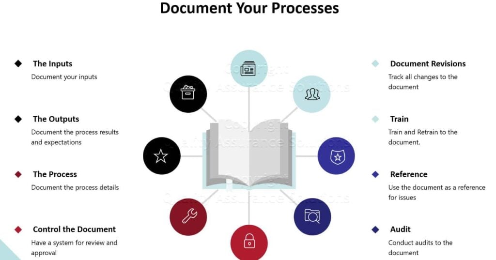
The Five Pillars of Manufacturing Documentation Control
| Manufacturing Pillar | Requirements For Manufacturing | Common Failures of Manufacturing | Manufacturing Solutions |
| Availability | Current versions accessible where needed | Outdated work instructions on shop floor | Electronic distribution with automatic updates |
| Protection | Prevent loss, confidentiality breaches | Uncontrolled copies shared via email | Role-based access controls |
| Version Control | Changes tracked with approval history | Multiple versions circulating simultaneously | Single source of truth with revision history |
| Retrievability | Records accessible for audits/investigations | Paper files lost or misfiled | Searchable electronic document management |
| Retention | Meet regulatory and customer requirements | Records destroyed too early | Automated retention scheduling with alerts |
The True Cost of Poor Manufacturing Documentation Control
Poor manufacturing documentation isn’t just an audit headache, it creates measurable business impact:
Rework and scrap: Using outdated specifications costs manufacturers an average of 2-5% of revenue annually
Audit findings: Major non-conformances can delay new business opportunities by 6-12 months
Customer complaints: Inability to demonstrate process control erodes customer confidence
Regulatory action: FDA 483 observations for documentation issues can escalate to warning letters
Material Traceability: The One-Up, One-Back Principle
Material traceability tracks the complete journey of raw materials from supplier receipt through production to finished goods shipment. Regulatory frameworks universally require what’s called “one-up, one-back” traceability:
One-back: Know exactly which supplier lot was consumed in each production batch
One-up: Know exactly which customer received each batch of finished goods
This bidirectional linkage enables rapid containment if material defects are discovered and is critical for safety-critical industries where recalls can cost millions.
Essential Manufacturing Traceability Data Elements
Incoming Manufacturing Material Records:
- Supplier name, lot number, certification
- Material grade and specifications
- Certificate of Analysis (CoA) or Certificate of Conformance (CoC)
- Receiving inspection results
- Internal lot assignment and storage location
In-Process Manufacturing Documentation:
- Work order number with material lot linkage
- Machine/workstation identifiers
- Operator identification at each operation
- Critical process parameters (temperature, pressure, time)
- In-process inspection and test results
Finished Manufactured Goods Records:
- Serial numbers or batch numbers
- Complete material genealogy (all lots consumed)
- Final inspection and test results
- Packaging and labeling documentation
- Shipment records with customer destination
Manufactured Material Genealogy Example
Finished Manufactured Good: Valve Assembly SN-2026-04472
| Manufacturing Component | Level 1 | Level 2 |
| Casting | Lot C-2026-0891 (ABC Foundry, Heat 47A) | Material: Brass C36000 Lot M-2026-2341 (MetalCorp) |
| Fasteners | Lot F-2026-556 (FastenRight, Grade 8.8) | – |
| Seals | Lot S-2026-112 (SealTech, Nitrile 70D) | – |
This level of traceability enables complete recall scope identification within minutes, not days.
Standards and Compliance Requirements by Industry
ISO 9001:2015 Foundation
ISO 9001 Clause 7.5 establishes the baseline for documented information control. Key requirements include:
- Identification and description
- Format and media
- Review and approval for adequacy before issue
- Control of changes with version identification

Aerospace: AS9100D Requirements
Aerospace quality management adds stringent requirements beyond ISO 9001:
- First Article Inspection (AS9102): Complete dimensional and documentation verification for initial production runs
- Configuration management: Control of design changes, deviations, and production permits
- Supplier flow-down: Traceability requirements must extend to subcontractors
- Counterfeit prevention: Documentation verifying material authenticity and chain of custody
- AS9100 traceability requirement: Records must be maintained for the specified life of the product plus one year, or as specified by the customer or regulatory authority.

Medical Device: ISO 13485 and FDA 21 CFR Part 820
Medical device manufacturing imposes the strictest traceability requirements:
- Unique Device Identification (UDI): FDA requires unique identifiers on medical devices for post-market surveillance
- Device History Record (DHR): Complete production record for each unit or batch
- Material biocompatibility: Documentation demonstrating material safety for intended use
- Sterilisation validation: Complete records of sterilisation process validation and monitoring
The FDA’s Quality System Regulation states that “each manufacturer shall establish and maintain procedures for identifying products during all stages of receipt, production, distribution, and installation to prevent mixups”.

Automotive: IATF 16949 Requirements
Automotive standards emphasize production part approval and continuous monitoring:
- Production Part Approval Process (PPAP): Comprehensive documentation package including dimensional results, material tests, process capability studies
- Control plans: Detailed documentation of quality controls at each process step
- Customer-specific requirements: OEMs like Toyota, Ford, and BMW impose additional traceability mandates
- Problem solving: Documented 8D or similar processes for containment and corrective action
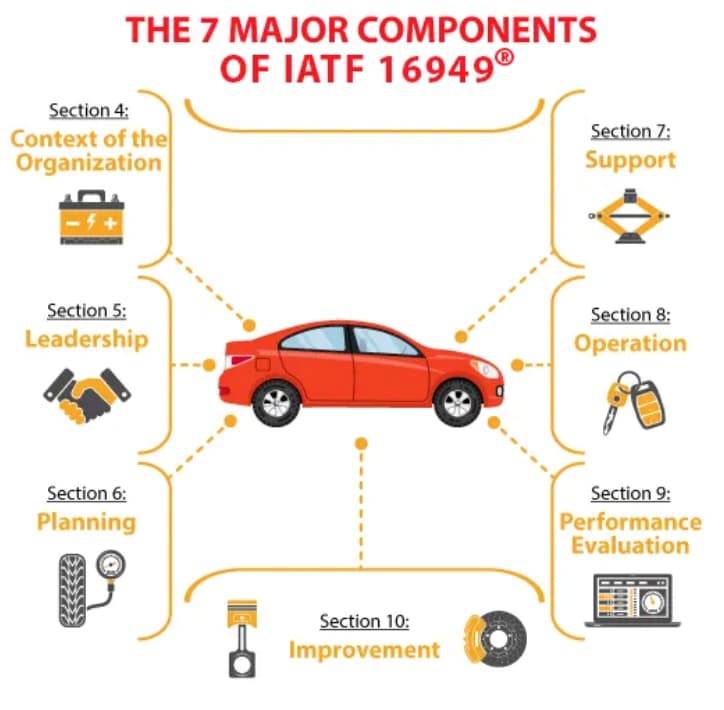
Implementing Documentation Control: A Step-by-Step Framework
Step 1: Document Classification Matrix
Organize documents by type to apply appropriate controls:
| Document Category | Examples | Control Requirements |
| Tier 1: Quality Manual | Policy, scope, management commitment | Controlled distribution, management approval |
| Tier 2: Procedures | Work instructions, SOPs, inspection procedures | Version control, training requirements |
| Tier 3: Records | Inspection reports, production logs | Retention control, authenticity protection |
| Tier 4: External | Customer specs, industry standards, regulations | Current version verification, change monitoring |
Step 2: Version Control Protocol
Implement consistent version identification:
Document Header Example:
Document ID: WI-QC-001
Title: Incoming Material Inspection Procedure
Version: Rev. 04
Effective Date: 2026-02-26
Supersedes: Rev. 03 (2025-11-15)
Approved by: J. Smith, Quality Manager
Page 1 of 12
Critical rules:
Never use “draft,” “preliminary,” or “uncontrolled” in released documents
Include revision history table showing what changed and why
Maintain master document register with current version status
Archive superseded documents but remove from active circulation
Step 3: Change Control Workflow
Every document change must follow a controlled process:
| Stage | Responsible Party | Action | Timeline |
| 1. Request | Any employee | Submit change request with justification | Day 1 |
| 2. Assessment | Document owner | Evaluate impact on operations, training needs | Day 2-3 |
| 3. Draft | Subject matter expert | Prepare revised document | Day 4-7 |
| 4. Review | Affected departments | Technical and operational review | Day 8-10 |
| 5. Approval | Authorized personnel | Final approval per approval matrix | Day 11 |
| 6. Release | Document control | Distribute and communicate changes | Day 12 |
| 7. Training | Supervisors | Train affected personnel on significant changes | Day 13-19 |
| 8. Verify | Quality | Confirm obsolete documents removed from use | Day 20 |
Step 4: Access Control Matrix
Control who can view, edit, and approve based on role:
| Role | View Access | Edit Access | Approve Authority |
| Production staff | Current work instructions only | No | No |
| Quality inspectors | All quality documents | Inspection records only | No |
| Department supervisors | Department documents | Draft changes | Department procedures |
| Quality manager | All documents | All documents | Quality system documents |
| General manager | All documents | Policy documents | All documents |
Building Material Traceability Systems
Receiving: The Traceability Foundation
Required documentation at receipt:
- Supplier packing slip with lot numbers
- Certificate of Analysis (CoA) or Certificate of Conformance (CoC)
- Material test reports (chemical composition, mechanical properties)
- Receiving inspection checklist completion
- Photographs of material condition and labeling
Best practice: Assign internal lot numbers immediately upon receipt, even when suppliers provide lot numbers. This prevents confusion when:
- Multiple suppliers use similar numbering schemes
- Supplier lot numbers are ambiguous or missing
- Material from different supplier lots is blended
In-Process Traceability Methods
Paper-based approach (smaller operations):
- Work order traveler with material lot fields
- Operator signatures at each operation
- Inspection stamps or stickers
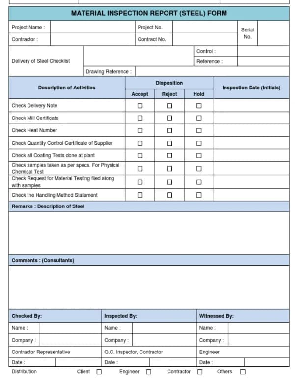
Electronic approach (larger operations):
- Barcode scanning at each operation
- RFID tags for automatic tracking
- MES integration for real-time genealogy
Critical requirement: At every operation, document which material lots were consumed and which finished goods lots were produced.
Finished Goods Identification Strategies
| Serialization Method | Format | Best For |
| Sequential | 0001, 0002, 0003… | Low volume, high value |
| Date-coded | 260226-001 (YYMMDD-XXX) | Time-sensitive traceability |
| Smart codes | PN-LOC-YY-XXXX (Product-Location-Year-Sequence) | Complex product families |
| Random unique | 8A4F92B7… | High security requirements |
Technology Solutions: From Paper to Digital
Electronic Document Management Systems (EDMS)
Modern EDMS platforms provide capabilities that paper systems cannot match:
| Feature | Business Benefit |
| Automatic version control | Prevents use of outdated documents |
| Electronic signatures | Speeds approvals, provides audit trails |
| Role-based access | Protects confidential information |
| Full-text search | Finds documents in seconds, not hours |
| Integration with ERP/MES | Links documents to transactions |
| Automated workflows | Routes documents for review and approval |
Leading EDMS providers: MasterControl, EtQ, Intellect, Documentum
Manufacturing Execution Systems (MES)
MES platforms bridge ERP and shop floor operations:
- Electronic work instructions with embedded quality checks
- Real-time production tracking with automatic material genealogy
- Quality enforcement (cannot proceed past incomplete inspections)
- Machine integration for automatic data collection
Benefit: Eliminates paper travelers, reduces transcription errors by 90%+, enables instant traceability queries.
ERP-Integrated Traceability
Enterprise Resource Planning systems with quality modules offer:
- Lot tracking from purchase order through shipment
- Quarantine management for inspection hold material
- Automatic traceability reports for customer or regulatory requests
- Supplier scorecards based on quality and delivery performance
Document Retention: How Long and Why
Retention Period Guidelines by Document Type
| Document Category | ISO 9001 | Aerospace | Medical Device | Automotive |
| Quality manual/procedures | Product life + 1 year | Product life + 1 year | Product life + 2 years | Product life + 1 year |
| Inspection records | Product life + 1 year | 10+ years | Product life + 2 years | 15 years |
| Material certifications | Product life + 1 year | Permanent | Permanent | Product life + 1 year |
| Calibration records | Current + 2 cycles | Current + 2 cycles | Current + 2 cycles | Current + 2 cycles |
| Training records | Employment + 3 years | Employment + 3 years | Employment period | Employment + 3 years |
| Internal audits | 3 years | 3 years | 3 years | 3 years |
Critical note: Always check customer-specific requirements, which may exceed regulatory minimums. Aerospace prime contractors often require 10-20 year retention for flight-critical components.
Conclusion
Selecting the optimal brass alloy for machining requires balancing machinability, corrosion resistance, regulatory compliance, and cost. C360 remains the production champion for general applications where lead content poses no concerns. C464 serves critical marine and heat transfer applications despite machining challenges. C485 bridges the gap between performance and environmental compliance.
By understanding these alloys’ distinct properties and following the machining guidelines outlined above, manufacturing engineers and buyers can optimize both part performance and production economics. The data-driven comparisons in this guide provide the foundation for informed material selection decisions.
For complex applications or high-volume production runs, we at Align Manufacturing work closely with our customers to ensure the right material and process decisions are made from the start. Leveraging our experience across precision machining operations and automation in the casting process, we focus on material selection, supplier control, and production discipline to deliver consistent and reliable results across a wide range of industries.
The small time investment in proper alloy selection pays dividends through improved quality, reduced scrap, and lower total manufacturing costs which is an approach we apply at Align Manufacturing to help our partners achieve better performance and long-term production efficiency.
FAQ: Documentation Control and Traceability
Q1: How long must we keep manufacturing records?
Minimum: Product life plus one year per ISO 9001. Aerospace and medical devices often require 7-10 years or permanent retention. Always verify customer-specific requirements.
Q2: Can we use electronic signatures For Manufacturing Documentation?
Yes, if your system meets regulatory requirements for electronic records (21 CFR Part 11 for medical devices, EU Annex 11 for pharmaceuticals). Must include audit trails, access controls, and signature authentication.
Q3: What if a supplier doesn’t provide lot numbers?
Assign internal receiving lot numbers and require suppliers to reference your lot numbers on their documentation. For critical materials, only use suppliers who can meet your traceability requirements.
Q4: How do we trace manufacturing material when multiple lots are blended?
Create a new lot number for the blend and document all contributing lots with quantities. Maintain blending calculations and ratios in your records.
Q5: What’s the difference between lot traceability and serialization?
Lot traceability tracks by batch (one record per lot). Serialization tracks individual units (unique ID per part). Serialization provides more granular traceability but requires more sophisticated systems.
Q6: Do we need traceability for all materials or just critical ones?
Regulations require traceability for materials affecting product conformity. Many companies extend to all materials for complete process control and to simplify systems.
Q7: How can small manufacturers afford traceability systems?
Start with paper travelers and lot tags. Implement barcode scanning as volume grows. Cloud-based MES systems like Tulip or ProShop offer affordable entry points starting at $500-1000/month.
Q8: What happens if we discover a traceability gap during an audit?
Immediate containment (hold suspect material), root cause analysis, corrective action implementation, and evidence of effectiveness. Transparent communication with auditors is essential.
Q9: Can traceability requirements be flown down to subcontractors?
Yes, and they should be. Include documentation and traceability requirements in purchase orders and audit subcontractors to verify compliance.
Q10: How do we maintain traceability during rework?
Document rework operations separately, linking back to original production records. Include rework rationale, process used, inspection results, and final disposition.
Brass Alloy Guide for Machining: Choosing C360, C464, C485 & More
Selecting the right brass alloy for your CNC machining project can mean the difference between profitable production runs and costly material failures. With dozens of brass grades available, each offering unique combinations of machinability, corrosion resistance, and mechanical properties, engineers and buyers face a complex decision matrix.
This guide cuts through the complexity. We’ll compare the most commonly machined brass alloys, including C360 free-cutting brass, C464 naval brass, and C485 lead-free alternatives, giving you the data you need to make informed material selections for your specific applications.
Why Brass Dominates CNC Machining
Brass has earned its place as one of the most machined metals in manufacturing. According to industry data, brass accounts for approximately 15% of all non-ferrous metal machining operations globally. The reasons are straightforward:
Superior Machinability: Most brass alloys machine at 100% machinability ratings compared to free-cutting steel, meaning faster production cycles and lower tool wear.
Excellent Surface Finish: Brass produces smooth, aesthetically pleasing surfaces without secondary finishing operations, critical for visible components.
Dimensional Stability: Brass maintains tight tolerances during and after machining, reducing scrap rates.
Corrosion Resistance: The copper content provides natural resistance to atmospheric corrosion, extending component lifespan.
Recyclability: Brass scrap retains high value, with recycling rates exceeding 90% in many manufacturing environments.
Understanding Brass Alloy Designations
Brass alloys follow the ASTM designation system, where “C” indicates a copper alloy, and the following numbers identify specific compositions. The first digit provides clues about the alloy family:
- C1xx: Commercially pure copper
- C2xx: Copper-zinc alloys (brasses)
- C3xx:Copper-zinc-lead alloys (leaded brasses)
- C4xx: Copper-zinc-tin alloys (tin brasses)
- C5xx: Copper-tin alloys (bronzes)
For machining applications, the C3xx and C4xx series dominate because lead and tin additions dramatically improve machinability.
C360 Free-Cutting Brass: The Machining Standard
C36000, commonly called free-cutting brass or engraving brass, represents the gold standard for machinability. This alloy contains approximately 61.5% copper, 35.5% zinc, and 3% lead.
Key Properties of C360 Brass
| Property | Value |
| Machinability Rating | 100% (baseline) |
| Tensile Strength | 48,000–55,000 psi |
| Yield Strength | 32,000–40,000 psi |
| Elongation | 15–20% |
| Hardness (Rockwell B) | 55–65 |
| Density | 0.307 lb/in³ |
Chemical Composition of C360 Brass
| Element | Percentage |
| Copper | 60.0–63.0% |
| Lead | 2.5–3.7% |
| Iron | 0.35% max |
| Zinc | Balance |
Best Applications For C360 Brass
C360 excels in high-speed screw machine operations and applications requiring:
- Complex geometries with tight tolerances
- Excellent surface finishes
- High production volumes
- Threaded components and fasteners
- Electrical connectors and terminals
- Decorative hardware
The lead content forms discrete particles that act as chip breakers and lubricants during machining. This produces small, manageable chips rather than long stringers that can entangle tooling and damage workpieces.
Cost Considerations For C360 Brass
C360 typically costs ฿278–฿357 per kg (₫189,000–₫243,000 per kg) ($3.50–$4.50 per lb), making it one of the more economical brass alloys. The high machinability reduces overall part costs through faster cycle times and extended tool life, even when accounting for the premium over lower-machinability alternatives.
Choose C360 Brass When:
- Maximum production speed is priority
- Parts require complex geometries
- Surface finish is critical
- Application allows lead content
- Cost minimization drives decisions
C464 Naval Brass: Corrosion Resistance Champion
C46400 naval brass combines good machinability with exceptional resistance to saltwater corrosion. The addition of approximately 1% tin to the copper-zinc matrix creates this marine-grade material.
Key Properties Of C464 Brass
| Property | Value |
| Machinability Rating | 30% of C360 |
| Tensile Strength | 58,000–75,000 psi |
| Yield Strength | 30,000–55,000 psi |
| Elongation | 18–40% |
| Hardness (Rockwell B) | 60–80 |
| Density | 0.304 lb/in³ |
Chemical Composition Of C464 Brass
| Element | Percentage |
| Copper | 59.0–62.0% |
| Tin | 0.50–1.0% |
| Lead | 0.20% max |
| Iron | 0.10% max |
| Zinc | Balance |
Best Applications For C464 Brass
Naval brass shines in aggressive environments:
- Marine hardware and fittings
- Heat exchanger tubes and plates
- Valve bodies and stems
- Pump components
- Propeller shafts
- Condenser tubes
- Desalination equipment
The tin addition creates a protective surface film that resists dezincification, which is a corrosion mechanism where zinc selectively leaches from the alloy, leaving porous copper. This makes C464 indispensable for seawater applications where C360 would fail prematurely.
Choose C464 Brass When:
- Saltwater exposure occurs
- Heat exchanger applications
- Dezincification resistance needed
- Moderate machinability is acceptable
- Long-term corrosion resistance justifies slower production
Machining Considerations For C464 Brass
C464’s 30% machinability rating means production runs take approximately three times longer than equivalent C360 parts. However, for marine applications, this trade-off is unavoidable. Machine shops should:
- Reduce cutting speeds by 30–40% compared to C360
- Use sharp carbide tooling
- Increase coolant flow to manage heat
- Expect shorter tool life between changes
C485 Lead-Free Brass: Environmental Compliance
C48500 addresses growing environmental and health concerns about lead in drinking water systems. This alloy maintains reasonable machinability while meeting lead-free requirements.
Key Properties Of C485 Brass
| Property | Value |
| Machinability Rating | 85–90% of C360 |
| Tensile Strength | 50,000–58,000 psi |
| Yield Strength | 34,000–42,000 psi |
| Elongation | 12–18% |
| Hardness (Rockwell B) | 60–70 |
| Density | 0.306 lb/in³ |

Chemical Composition Of C485 Brass
| Element | Percentage |
| Copper | 59.0–62.0% |
| Tin | 0.50–0.75% |
| Lead | 0.09% max (lead-free) |
| Iron | 0.10% max |
| Zinc | Balance |
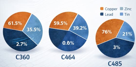
Best Applications For C485 Brass
C485 serves lead-free requirements in:
- Potable water fittings and valves
- Plumbing fixtures
- Food processing equipment
- Medical devices
- Children’s toys
- Electrical components
Choose C485 Brass When:
- Potable water contact occurs
- Lead-free compliance required
- Food/medical applications
- Balanced machinability and compliance needed
- Premium cost acceptable for regulatory adherence
The Lead-Free Challenge
Eliminating lead while maintaining machinability required metallurgical innovations. C485 achieves this through:
- Controlled tin additions for chip breaking
- Tighter composition controls
- Specialized heat treatment processes
While not quite matching C360’s legendary machinability, C485’s 85–90% rating makes it production-friendly for most applications. The cost premium of approximately 15–20% over C360 is often justified by regulatory compliance.
Comprehensive Brass Alloy Comparison
| Property | C360 Brass | C464 Brass | C485 Brass |
| Machinability | 100% | 30% | 85–90% |
| Corrosion Resistance | Good | Excellent | Good |
| Marine Suitability | Poor | Excellent | Moderate |
| Lead Content | 2.5–3.7% | <0.20% | <0.09% |
| Cost (per kg) | ฿270–฿350/kg, ₫165,000–₫212,000/kg ($3.50–$4.50/lb) | ฿310–฿425/kg, ₫189,000–₫260,000/kg ($4.00–$5.50/lb) | ฿325–฿450/kg, ₫198,000–₫275,000/kg ($4.20–$5.80/lb) |
| Typical Lead Time | Standard | Standard | Longer |
| Tensile Strength | 48–55 ksi | 58–75 ksi | 50–58 ksi |
| Primary Advantage | Machinability | Corrosion resistance | Lead-free compliance |
Machining Best Practices by Alloy
C360 Machining Parameters
- Cutting Speed: 300–500 SFM (surface feet per minute)
- Feed Rate: 0.005–0.015 in/rev
- Depth of Cut: 0.050–0.200 inches
- Tool Material: Carbide or coated HSS
- Coolant: Soluble oil or synthetic
C464 Machining Parameters
- Cutting Speed: 150–250 SFM
- Feed Rate: 0.003–0.010 in/rev
- Depth of Cut: 0.030–0.100 inches
- Tool Material: Sharp carbide
- Coolant: High-flow soluble oil
C485 Machining Parameters
- Cutting Speed: 250–400 SFM
- Feed Rate: 0.004–0.012 in/rev
- Depth of Cut: 0.040–0.150 inches
- Tool Material: Carbide with polished flutes
- Coolant: Soluble oil recommended
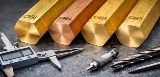
Cost-Performance Analysis
Material selection involves more than per-pound pricing. Consider total cost of ownership:
C360 Total Cost Example:
- ฿159 (₫49,000) ($2.00)
- Machining time:
฿108 (₫73,500) ($3.00) - Tool wear:
฿9 (₫6,100) ($0.25) - Total per part: ฿189 (₫128,600) ($5.25)
C464 Total Cost Example:
- Material:
฿188 (₫58,300) ($2.38) - Machining time:
฿324 (₫220,500) ($9.00) - Tool wear:
฿27 (₫18,400) ($0.75) - Total per part: ฿437 (₫297,200) ($12.13)
C485 Total Cost Example:
- Material:
฿198 (₫61,300) ($2.50) - Machining time:
฿135 (₫91,900) ($3.75) - Tool wear:
฿13 (₫8,600) ($0.35) - Total per part: ฿238 (₫161,800) ($6.60)
For marine applications, C464’s additional $6.88 per part is justified by corrosion resistance. For lead-free plumbing, C485’s $1.35 premium over C360 is unavoidable for regulatory compliance.
Additional Brass Alloys for Specialized Applications
Beyond the three primary alloys covered above, several specialized brass grades deserve consideration for specific manufacturing scenarios.
C353 High-Leaded Brass
C35300 offers even higher lead content than C360, pushing machinability beyond standard ratings. With 3.5–4.5% lead content, this alloy produces ultra-small chips ideal for intricate Swiss-style machining operations.
Applications:
- Watch components requiring micro-precision
- Medical instrument fittings
- Electronic connector pins
- Optical equipment hardware
Considerations: The higher lead content raises environmental handling concerns and restricts C353 to non-potable water applications. However, for pure machining performance in complex geometries, few alloys compete.
C385 Architectural Bronze
Despite its name, C385 is actually a brass alloy containing 55–60% copper, 39–42% zinc, and 2.5–3.5% lead. The “bronze” designation stems from its historical use and color rather than composition.
Properties:
- Good machinability (90% of C360)
- Excellent hot working characteristics
- Attractive golden color for decorative applications
- Good cold working properties
Applications:
- Ornamental hardware
- Hinges and decorative fittings
- Trim and molding
- Nameplates and plaques
C693 Eco Brass
C69300 represents the next generation of lead-free brass alloys, achieving machinability ratings approaching 95% of C360 through bismuth and selenium additions rather than tin.
Advantages over C485:
- Superior machinability (95% vs 85–90%)
- Better chip formation
- Lower tool wear
- Excellent for high-speed machining
Cost: C693 commands a 25–30% premium over C360, but for high-volume lead-free production, the improved machinability often justifies the expense through reduced cycle times.
Heat Treatment and Stress Relieving
While brass alloys are generally used in their as-machined condition, certain applications benefit from thermal processing.
Stress Relieving
Machining operations induce residual stresses that can cause distortion during service or subsequent processing. Stress relieving at 400–500°F for 1–2 hours reduces these stresses without significantly affecting mechanical properties.
When to stress relieve:
- Large, thin-walled components
- Parts requiring tight flatness tolerances
- Components undergoing secondary welding
- Precision assemblies requiring long-term dimensional stability
Annealing
For applications requiring extensive cold forming after machining, annealing at 800–1,000°F softens the material. However, annealed brass machines poorly compared to work-hardened or half-hard tempers.
Best practice: Complete all machining operations before final annealing if possible.
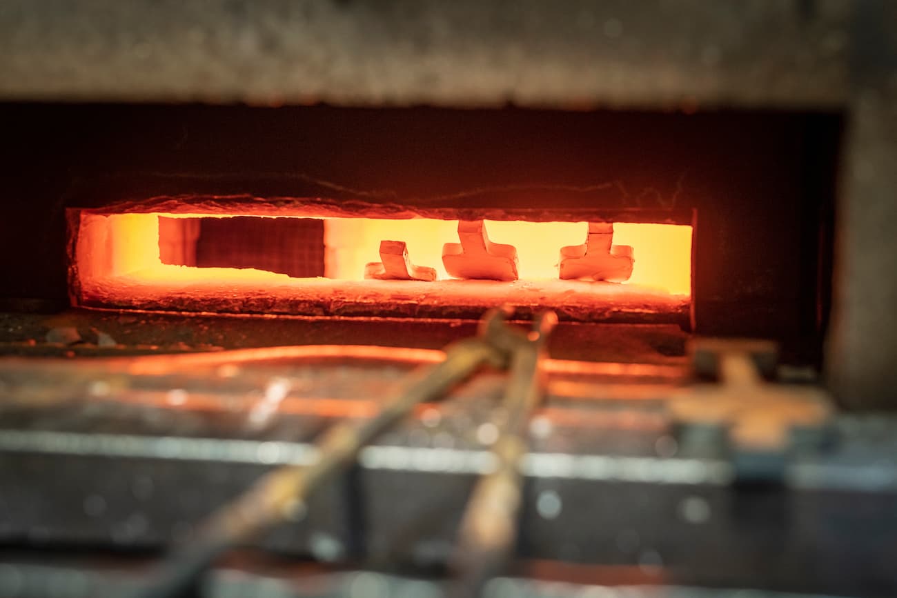
Quality Control and Testing
Ensuring brass alloy quality requires appropriate testing protocols.
Chemical Verification
For critical applications, request mill test certificates verifying:
- Exact composition percentages
- Lead content (especially important for lead-free requirements)
- Trace element limits
Mechanical Testing
Standard tensile testing confirms:
- Ultimate tensile strength within specification
- Yield strength adequate for application
- Elongation for formability requirements
Dimensional Inspection
Brass bar stock should arrive within specified tolerances:
- Diameter: typically ±0.002 to ±0.005 inches
- Straightness: 0.025 inches per foot maximum
- Corner radii per specification
Environmental and Regulatory Considerations
Material selection increasingly involves regulatory compliance.
RoHS Compliance
The Restriction of Hazardous Substances directive limits lead content in electrical and electronic equipment. C360 and other leaded brasses face restrictions in:
- Consumer electronics
- Electrical distribution equipment
- Automotive components (increasingly)
Prop 65 Compliance (California)
Products containing leaded brass sold in California require warning labels. C485 and C693 eliminate this requirement.
NSF/ANSI 61 Certification
For potable water applications, alloys must meet NSF/ANSI 61 standards. C485 is certified; C360 is not suitable for drinking water contact.
Supply Chain and Availability
Understanding material availability helps production planning.
Standard Forms
Brass alloys are readily available as:
- Round bar: 1/8″ to 6″ diameter
- Hexagonal bar: 1/4″ to 3″ across flats
- Square bar: 1/4″ to 2″
- Rectangular bar: Various dimensions
- Hollow bar: For reducing material waste
Lead Times
- C360: Standard stock item, 1–2 weeks
- C464: Readily available, 1–3 weeks
- C485: Longer lead times, 3–6 weeks due to lower demand volumes
Pricing Trends
Brass pricing tracks copper commodity markets with zinc and lead premiums. Over the past five years, brass alloys have shown 3–5% annual price increases, with greater volatility for lead-free grades as environmental regulations tighten.
Design for Machining: Brass-Specific Guidelines
Optimizing part designs for brass alloys improves manufacturability.
Wall Thickness
Brass allows thinner walls than steel due to its superior machinability:
- Minimum wall thickness: 0.020 inches for C360
- Preferred minimum: 0.030 inches for rigidity
- Thinner walls possible with C464 due to higher strength
Internal Features
- Threaded holes: Brass taps easily; smaller pilot holes possible than steel
- Undercuts: Standard designs work well
- Grooves: Sharp corners acceptable in brass
External Features
- Knurling: Excellent in brass due to material softness
- Engraving: C360 particularly suited for detailed engraving
- Cross-holes: Minimal burr formation compared to steel
Surface Finish Requirements
Specify finishes appropriately:
- As-machined: Adequate for most functional parts
- Tumbled: Removes burrs and improves appearance
- Polished: Required for decorative applications
- Plated: Nickel, chrome, or gold plating common for brass
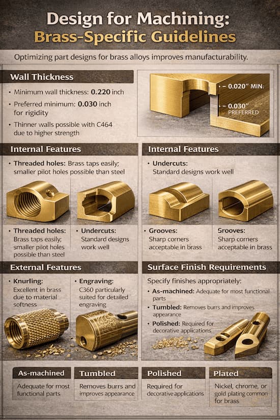
Summary and Quick Reference
| Application Requirement | Recommended Alloy |
| Maximum machinability | C360 |
| Marine/saltwater exposure | C464 |
| Lead-free compliance | C485 or C693 |
| Decorative/decorative | C385 |
| Micro-precision parts | C353 |
| High-speed lead-free | C693 |
| General purpose | C360 |
| Heat exchangers | C464 |
| Potable water | C485 |
Material selection ultimately balances performance requirements, manufacturing constraints, regulatory compliance, and cost. This guide provides the foundational knowledge for making informed brass alloy selections that optimize your CNC machining operations.
For applications not clearly addressed above, consult with material engineers or brass suppliers who can provide application-specific guidance based on your unique requirements and production environment.
Conclusion
Selecting the optimal brass alloy for machining requires balancing machinability, corrosion resistance, regulatory compliance, and cost. C360 remains the production champion for general applications where lead content poses no concerns. C464 serves critical marine and heat transfer applications despite machining challenges. C485 bridges the gap between performance and environmental compliance.
By understanding these alloys’ distinct properties and following the machining guidelines outlined above, manufacturing engineers and buyers can optimize both part performance and production economics. The data-driven comparisons in this guide provide the foundation for informed material selection decisions.
For complex applications or high-volume production runs, we at Align MFG work closely with our customers to ensure the right material and process decisions are made from the start. With our focus on precision machining in Vietnam, Thailand and India, we combine material expertise, supplier control, and production discipline to deliver consistent, reliable results across a wide range of industries.
The small time investment in proper alloy selection pays dividends through improved quality, reduced scrap, and lower total manufacturing costs, making it a critical step in any successful machining project.
Frequently Asked Questions
What is the most machinable brass alloy?
C360 free-cutting brass holds the industry standard with a 100% machinability rating. The 3% lead content creates optimal chip formation and tool life. No other brass alloy matches its production efficiency.
Can I use C360 for marine applications?
No. C360 lacks adequate corrosion resistance for saltwater environments. The zinc content makes it susceptible to dezincification. For marine applications, C464 naval brass is the appropriate choice despite its lower machinability.
Is lead-free brass harder to machine?
Generally yes, but the difference is manageable. C485 lead-free brass achieves 85–90% of C360’s machinability. Modern lead-free alloys have improved significantly through tin additions and metallurgical refinements. The machining trade-off is acceptable for regulatory compliance.
How do I prevent corrosion when machining brass?
Use appropriate coolants and avoid contamination. For C360 and C485, standard soluble oils work well. For C464 in marine applications, ensure complete removal of machining residues. Consider passivation treatments for critical corrosion-resistant components.
What brass alloy should I choose for drinking water fittings?
C485 lead-free brass is required for potable water applications under modern regulations. Its lead content below 0.09% meets safety standards while maintaining reasonable machinability for production environments.
Can brass alloys be welded after machining?
C360 is generally considered unweldable due to lead content causing cracking. C464 can be welded using appropriate procedures, though heat-affected zones require consideration. C485 offers better weldability than C360. For welded assemblies, consider starting with C464 or C485 stock.
What surface finishes can I achieve with brass machining?
C360 produces the finest as-machined surfaces, often achieving 32–63 microinch Ra without additional finishing. C464 and C485 typically achieve 63–125 microinch Ra. All brass alloys accept plating, painting, and chemical finishing if required.
Implementing ISO 9001 QMS for Job Shop Manufacturing: Step-by-Step Guide
What Defines Job Shop Manufacturing And ISO 9001 QMS
Job shops are manufacturing environments that specialize in custom, low-volume production, where each job may have unique specifications, processes, and routing. Unlike mass production facilities, they operate with high variability and must adapt quickly to changing customer requirements. An ISO 9001 Quality Management System (QMS) is a structured framework that helps businesses standardize processes, ensure consistent quality, and drive continuous improvement. For job shops, an effective QMS provides the balance between flexibility and control, allowing them to manage complexity while maintaining reliability and customer satisfaction.
Introduction: Why Job Shop Manufacturing Needs a Different Approach to ISO 9001
Job shops need a different approach to ISO 9001 because they operate in a world of relentless change and variety, producing custom parts in small batches under high-mix, low-volume conditions with constantly evolving customer requirements. Mass production facilities can apply rigid, standardized processes suited to repeating the same parts daily, but job shops’ fluid operations make these traditional ISO 9001 implementations, geared toward repetitive manufacturing—ineffective, often leading to bloated documentation, inflexible workflows, and stifled agility.
Despite these challenges, ISO 9001 certification (or internal implementation) is now non-negotiable for securing contracts with OEMs in automotive, aerospace, medical devices, and industrial equipment sectors. The standard’s core value such as delivering consistent processes, continuous improvement via PDCA cycles, and proven customer satisfaction remains vital, but only when tailored to job shop dynamics, emphasizing risk-based thinking (Clause 6) over prescriptive controls.
This tailored strategy avoids shoehorning production-heavy QMS templates into variable job shop realities, instead creating a lean, adaptable system that scales with diverse orders, integrates with ERP tools like JobBOSS or E2 Shop System, and boosts competitiveness without sacrificing speed or customization.
Understanding the Job Shop Challenge
What Makes Job Shops Different
Before diving into implementation, it’s essential to understand why job shops require a tailored approach:
1. Manufacturing Process Variability
- Mass production: Same process, same parts, continuous improvement
- Job shops: Different processes for every job, frequent setup changes, variable routings
2. Documentation Burden For Manufacturing
- Mass production: Document once, run forever
- Job shops: Each job may require unique work instructions, inspection plans, and quality records
3. Manufacturing Customer Diversity
- Mass production: Standard products, standard requirements
- Job shops: Custom specifications, unique customer requirements, varying industry standards
4. Volume and Mix Of Manufacturing
- Mass production: High volume, low variety, statistical process control is straightforward
- Job shops: Low volume, high variety, SPC is challenging, job-specific controls needed
5. Quoting and Planning For Manufacturing
- Mass production: Stable forecasts, predictable capacity
- Job shops: Uncertain demand, complex quoting, capacity planning difficulties
The Consequence: Traditional ISO 9001 Approaches Fail
Many job shops attempt ISO 9001 implementation using approaches designed for repetitive manufacturing:
- Rigid process documentation that can’t adapt to job variability
- Generic work instructions that provide no value for specific jobs
- Overly complex systems that slow down quoting and production
- Documentation-heavy approaches that burden staff without quality benefits
The result? Either a cumbersome system that employees resist, or a “checkbox” system that satisfies auditors but doesn’t improve quality or efficiency.
This guide takes a different approach: building a QMS that leverages job shop strengths while addressing unique challenges.
Step 1: Secure Leadership Commitment and Define Scope
Leadership Commitment: The Foundation of Success
ISO 9001 implementation cannot succeed without genuine leadership commitment. This is not merely a financial or resource commitment, it’s a cultural commitment to quality as a core business strategy.
Leadership responsibilities include:
- Establishing Manufacturing quality policy that reflects job shop realities
- Setting Manufacturing quality objectives that are meaningful and measurable
- Allocating resources for implementation and maintenance
- Participating in management reviews and continuous improvement
- Modeling quality-focused behavior throughout the organization
Practical tip for job shops: The quality policy should explicitly acknowledge job shop variability while committing to consistent quality outcomes. Example:
“We commit to delivering quality custom-manufactured components that meet or exceed customer specifications, regardless of job complexity or volume. Our quality management system provides the framework for consistent performance across diverse products while maintaining the flexibility our customers require.”
Defining Job Shop Manufacturing Scope: What’s In and What’s Out
ISO 9001 requires a clear definition of the QMS scope. For job shops, this means:
Include in Manufacturing scope:
- Core manufacturing processes (machining, fabrication, assembly)
- Quoting and order processing
- Purchasing and supplier management
- Quality control and inspection
- Delivery and post-delivery support
Consider carefully:
- Design activities (if applicable, adds complexity)
- Outsourced processes (must be controlled)
- Secondary locations or remote operations
Manufacturing Scope statement example:
“The Quality Management System of [Company Name] applies to the provision of custom CNC machining, fabrication, and assembly services for industrial, automotive, and aerospace customers. The QMS covers all activities from quotation through delivery, including purchasing of materials and subcontracted processes, but excludes product design activities which remain customer responsibility.”
Implementation Planning For Job Shop Manufacturing
Before proceeding, establish:
- Implementation timeline (typically 6-12 months for job shops)
- Resource requirements (dedicated implementation team, training budget)
- Certification goals (if certification is desired)
- Key milestones and review points
Job shop tip: Don’t rush implementation. The complexity of job shop operations requires thoughtful system design. A poorly designed QMS that doesn’t fit your operations will be resisted and ultimately fail.
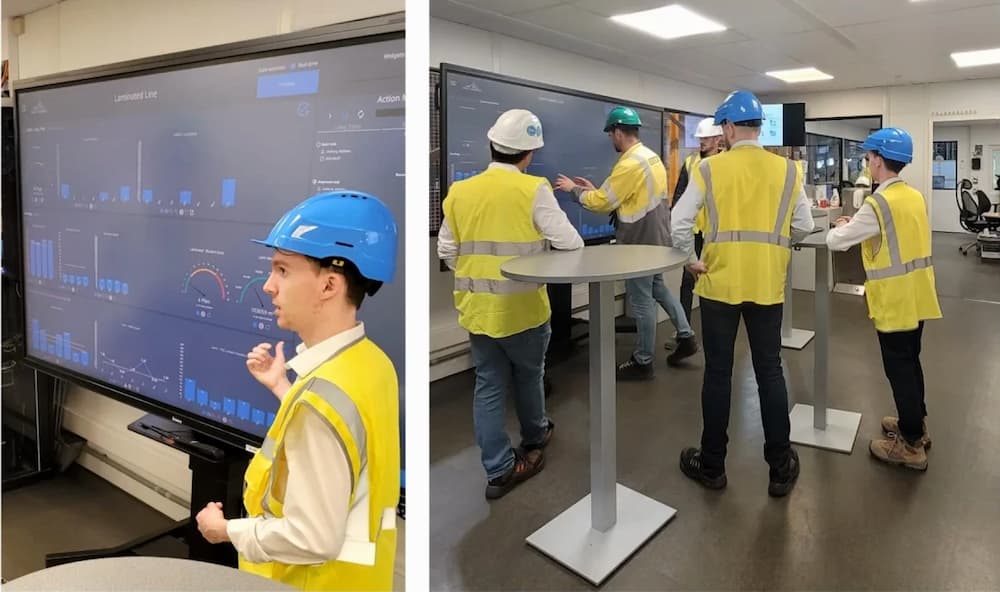
Step 2: Conduct Gap Analysis and Risk Assessment
Gap Analysis: Where Are You vs. Where You Need To Be In Job Shop Manufacturing
A gap analysis compares your current quality practices against ISO 9001 requirements. For job shops, focus on:
Documentation gaps:
- What procedures exist? What’s missing?
- Are current documents used? Are they effective?
- What’s documented vs. “tribal knowledge”?
Manufacturing Process gaps:
- Are processes defined and understood?
- Are responsibilities clear?
- Are there control points for quality?
Record Manufacturing gaps:
- What records are kept? What’s missing?
- Are records accessible and retrievable?
- Is there evidence of conformity?
Job shop manufacturing specific considerations:
- How are job-specific requirements captured and communicated?
- Is there consistency in quoting and planning?
- Are quality issues tracked and analyzed?
- Is customer feedback systematically collected?
Risk-Based Thinking: The Core of ISO 9001:2015
ISO 9001:2015 emphasizes risk-based thinking throughout the QMS. For job shops, this means identifying and addressing risks that could impact quality, delivery, or customer satisfaction.
| Risk Category | Examples | Mitigation Strategies |
| Quoting | Underestimating complexity, missing requirements | Standardized quote review, technical review process |
| Planning | Capacity conflicts, setup time underestimation | Visual scheduling, load leveling, buffer management |
| Purchasing | Material defects, supplier delays | Approved supplier list, incoming inspection |
| Manufacturing | Setup errors, process variation, tool wear | Setup checklists, in-process inspection, SPC where applicable |
| Inspection | Measurement error, missed defects | MSA studies, sampling plans, defined acceptance criteria |
| Delivery | Packaging damage, shipping errors | Packaging specs, shipping checklists, tracking |
| Communication | Misunderstood requirements, unclear specifications | Customer requirement review, clarification process |
Risk assessment approach for job shops manufacturing:
Rather than extensive risk documentation for every possible scenario, focus on:
- Key manufacturing processes with significant quality or delivery impact
- Recurring manufacturing issues from customer complaints or internal failures
- High-value or critical customer manufacturing jobs
- New manufacturing processes, materials, or customers
Document risk assessments in a format that’s practical and usable, not bureaucratic. A simple risk register with mitigation actions is often sufficient.

Step 3: Design Your Documented Information System
The Documentation Challenge for Job Shop Manufacturing
ISO 9001 requires “documented information” where necessary for QMS effectiveness. For job shops, the challenge is creating documentation that’s:
- Flexible enough to accommodate job variety
- Specific enough to ensure consistent quality
- Simple enough that people actually use it
- Accessible enough to be useful on the shop floor
Core Documentation for Job Shop Manufacturing ISO 9001
Required documented information includes:
- Quality Policy (Clause 5.2)
- Quality Objectives (Clause 6.2)
- Scope of QMS (Clause 4.3)
- Processes needed for QMS (Clause 4.4)
Documented procedures typically needed:
- Document Control – How documents are approved, distributed, and updated
- Record Control – How records are identified, stored, and retained
- Control of Nonconforming Output – How defects are identified, segregated, and dispositioned
- Internal Audit – How audits are planned, conducted, and followed up
- Corrective Action – How problems are investigated and resolved
Management Review – How the QMS is reviewed at regular intervals
Job shop specific documentation:
- Quoting Process – How quotes are prepared, reviewed, and approved
- Job Planning Process – How jobs are planned, routed, and scheduled
- Purchasing Process – How suppliers are selected and material is purchased
- Manufacturing Process – General manufacturing controls (job-specific via work instructions)
- Inspection Process – How inspections are planned and conducted
- Customer Communication – How requirements are clarified and changes managed
The Job Shop Manufacturing Documentation Strategy: Flexible Framework + Job-Specific Details
The key to successful job shop documentation is separation:
Level 1:Manufacturing Quality Manual (optional but recommended)
- Overall QMS scope and structure
- Process interactions
- Exclusions and justifications
Level 2: Procedures (general processes)
- Quoting procedure
- Planning procedure
- Purchasing procedure
- Inspection procedure
- General manufacturing controls
Level 3: Work Instructions (job-specific)
- Setup sheets
- Job-specific inspection plans
- Special process instructions
- Packaging instructions
Level 4: Records (evidence of conformity)
- Inspection records
- Route sheets/travelers
- Nonconformance reports
- Customer communications
Critical principle: Procedures define *how* work is done consistently. Work instructions define *what* is done for specific jobs. Don’t try to document every possible job variation in procedures, that’s what work instructions are for.
Practical Documentation Tips for Job Shops
1. Start with existing documents
Don’t reinvent. Review what you already have:
- Quote templates
- Shop travelers/route sheets
- Inspection sheets
- Setup sheets
- Customer requirements checklists
These often need only minor modifications to meet ISO 9001 requirements.
2. Use visual documentation
- Photos and videos for setup instructions
- Visual work instructions where helpful
- Color-coded routers or travelers
- Visual management boards
3. Keep it accessible
- Digital documents on shop floor tablets or computers
- Laminated quick reference cards
- QR codes linking to full instructions
- Simple, clear language
4. Make it useful
- Documents should solve problems, not create them
- If employees don’t use a document, find out why
- Involve shop floor staff in document development
- Regular reviews for relevance and usefulness
Step 4: Implement Manufacturing Process Controls
Manufacturing Quoting and Order Processing
The quoting process in job shops is critical, it’s where customer requirements are first translated into internal specifications.
Key controls:
1. Customer manufacturing requirement review
- Standard checklist of manufacturing requirements to verify
- Technical feasibility assessment
- Clarification process for unclear requirements
- Documentation of special requirements
2. Manufacturing Quote preparation
- Standardized quote template
- Clear assumptions and exclusions
- Lead time and delivery commitments
- Terms and conditions
3. Quote review and approval
- Technical review for complex jobs
- Capacity check before commitment
- Management approval for large or risky quotes
- Documentation of approval
4. Order confirmation
- Acknowledgment of purchase order
- Verification against quote
- Communication of any discrepancies
- Entry into production planning system
Production Planning and Control
Job shop planning is inherently challenging due to variability. ISO 9001 requires controlled conditions for production, so here’s how to achieve that flexibility within control.
Planning controls:
1. Job planning process
- Router/traveler creation
- Material requirements planning
- Outsourcing decisions and planning
- Capacity loading
2. Production scheduling
- Visual scheduling board or system
- Priority rules (first-in-first-out, earliest due date, etc.)
- Buffer management for constraint resources
- Daily production meetings
3. Work instructions
- Setup sheets with photos/diagrams
- In-process inspection requirements
- Special handling or tooling requirements
- Reference to customer specifications
4. In-process monitoring
- First-piece inspection
- In-process checks at defined operations
- Statistical process control where volume supports it
- Operator self-inspection
Purchasing and Supplier Control
Job shops are heavily dependent on material suppliers and may use subcontracted processes (heat treat, plating, etc.).
Supplier controls:
1. Approved supplier list
- Criteria for supplier approval
- Evaluation records
- Performance monitoring
- Re-evaluation triggers
2. Purchase order controls
- Clear specification of requirements
- Reference to applicable specifications
- Quality requirements (material certs, inspection reports)
- Approved suppliers only
3. Incoming inspection
- Receiving inspection procedures
- Material certification verification
- Dimensional/layout inspection as appropriate
- Nonconforming material segregation
4. Supplier performance
- On-time delivery tracking
- Quality metrics (defects, returns)
- Periodic supplier reviews
- Corrective action when needed
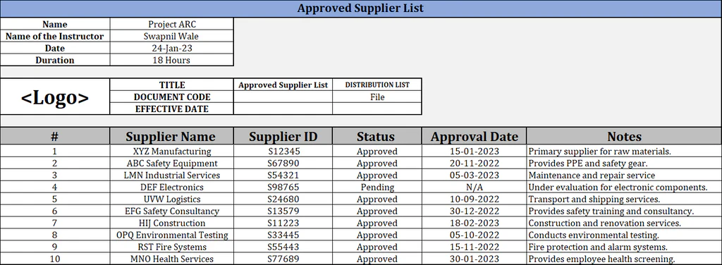
Inspection and Testing
Inspection in job shops must balance thoroughness with practicality.
Inspection planning:
1. Inspection plans
- Define what to inspect (characteristics)
- Define when to inspect (in-process, final, receiving)
- Define how to inspect (method, equipment)
- Define acceptance criteria
2. Inspection resources
- Calibrated measurement equipment
- Qualified inspectors
- Appropriate environment
- Documented procedures
3. Inspection records
- Objective evidence of conformity
- Measurement data
- Inspector identification
- Date and job reference
Job shop inspection strategy:
- Risk-based approach: More inspection for critical characteristics, new processes, or problem history
- First-piece inspection for setup verification
- In-process checks at operations where defects are likely
- Final inspection before shipment
- Layout inspection for first articles or complex parts

Control of Nonconforming Outputs
Nonconforming products are inevitable in manufacturing. The key is controlled handling.
Nonconformance process:
1. Identification
- Clear labeling or tagging
- Physical segregation
- Electronic system flagging
2. Documentation
- Nonconformance report
- Description of defect
- Quantity affected
- Job/customer reference
3. Disposition
- Rework (with re-inspection)
- Repair (with customer approval if required)
- Scrap
- Concession/use-as-is (with customer approval)
4. Corrective action
- Root cause analysis
- Action to prevent recurrence
- Verification of effectiveness
Job shop consideration: Given job variety, root cause analysis should distinguish between:
- Job-specific causes (one-time issues)
- Systemic causes (recurring problems requiring process changes)
Step 5: Build Measurement and Improvement Systems
Monitoring and Measurement
ISO 9001 requires monitoring and measurement of QMS performance. For job shops, focus on metrics that drive improvement.
Key metrics for job shops:
| Metric Category | Examples | Purpose |
| Customer Satisfaction | On-time delivery, quality complaints, returns, surveys | External performance view |
| Internal Quality | First-pass yield, scrap rate, rework hours, defect Pareto | Process effectiveness |
| Efficiency | Quote win rate, setup time, throughput, utilization | Operational performance |
| Supplier Performance | On-time delivery, quality acceptance, lead times | Supply chain health |
| QMS Effectiveness | Audit findings, corrective actions, training completion | System health |
2. Automate where possible – Use job shop software/ERP for data collection.
3. Visual management – Post key metrics where employees see them.
4. Trend analysis – Look at trends over time, not just current numbers.
5. Action-oriented – Metrics should drive action, just data collection.
Internal Audit
Internal audits verify that the QMS is effectively implemented and maintained.
Job shop audit approach:
1. Risk-based audit program
- Focus on high-risk processes
- Vary depth based on process importance and history
- Include customer-complaint areas
2. Practical audits
- Talk to people doing the work
- Observe actual practices vs. documented procedures
- Review records for evidence
- Look for improvement opportunities, not just compliance
3. Competent auditors
- Train internal auditors
- Ensure objectivity (don’t audit own work)
- Provide auditor resources/tools
4. Effective reporting
- Clear audit findings
- Root cause analysis
- Corrective action tracking
- Management review of audit results
Management Review
Management review is the mechanism for ensuring the QMS remains suitable, adequate, and effective.
Inputs to management review:
1. Status of actions from previous reviews
2. Changes in external/internal issues relevant to QMS
3. Information on performance and trends:
- Customer satisfaction
- Quality performance
- Process performance
- Product conformity
- Supplier performance
- Audit results
4. Adequacy of resources
5. Effectiveness of actions taken
6. Risks and opportunities
Outputs from management review:
- Opportunities for improvement
- Changes needed to QMS
- Resource needs
Job shop tip: Keep management reviews practical and focused. Don’t just review data, make decisions about improvements needed.
Continuous Improvement
ISO 9001 requires continual improvement of the QMS suitability, adequacy, and effectiveness.
Improvement sources:
- Customer feedback – Complaints, surveys, returns
- Internal issues – Nonconformances, audit findings
- Data analysis – Trends, patterns, opportunities
- Risk assessment – Emerging risks requiring action
- Management review – Strategic improvement decisions
- Technology – New capabilities enabling improvement
Job shop improvement priorities:
Given resource constraints, focus improvement efforts on:
- Recurring problems (high-impact, frequent issues)
- Customer-critical processes
- Bottlenecks constraining throughput
- Areas with high variability or uncertainty
Practical improvement tools:
- Pareto analysis (focus on vital few)
- 5-Why analysis (simple root cause)
- Process mapping (understand current state)
- PDCA cycle (Plan-Do-Check-Act)
Step 6: Prepare for Certification (If Desired)
Certification vs. Implementation-Only
ISO 9001 implementation provides value regardless of certification. Consider:
Implementation without certification:
- Lower cost (no certification body fees)
- No external audit pressure
- Self-declaration of conformity
- May satisfy some customers
- Full internal benefits of structured QMS
Certification:
- Third-party validation
- Often required by major OEMs
- Marketing advantage
- External audit discipline
- Continuous improvement pressure
Certification Process Overview
If pursuing certification:
1. Select certification body
- Accredited body (ANAB, UKAS, etc.)
- Industry experience
- Competitive pricing
- Geographic coverage
2. Stage 1 audit (documentation review)
- Auditor reviews documentation
- Identifies major gaps
- Provides improvement opportunities
- Must complete before Stage 2
3. Stage 2 audit (implementation audit)
- On-site audit of full QMS
- Interviews with personnel
- Observation of processes
- Review of records
- Identification of nonconformities
4. Certification decision
- Corrective actions for any nonconformities
- Certification body review
- Certificate issuance (if approved)
5. Surveillance audits
- Annual audits to maintain certification
- Partial QMS coverage each visit
- Full QMS over 3-year cycle
Job Shop Certification Tips
Before the audit:
- Conduct internal audit to find and fix issues
- Ensure records are complete and organized
- Brief employees on auditor interactions
- Prepare examples of continuous improvement
During the audit:
- Be honest and transparent
- Show how you meet requirements (not just documents)
- Demonstrate process knowledge
- Address findings promptly
Common job shop nonconformities:
- Inadequate job planning documentation
- Missing inspection records
- Incomplete corrective actions
- Training records gaps
- Document control issues
Step 7: Maintain and Improve Your QMS
The Real Work Begins After Implementation
Implementing ISO 9001 is not a project with an end date, it’s the very beginning of a continuous journey. The initial implementation creates the framework; ongoing operation refines and improves it.
Maintenance activities:
- Regular internal audits (quarterly or semi-annually)
- Management reviews (quarterly recommended)
- Corrective action follow-up
- Document updates as processes change
- Training for new employees
- Customer feedback monitoring
- Metrics review and improvement
Evolving Your QMS
As your job shop grows and changes, your QMS should evolve:
Triggers for QMS updates:
- New processes or capabilities
- New customer requirements
- New regulatory requirements
- Organizational changes
- Technology changes
- Continuous improvement findings
Avoiding QMS stagnation:
- Regular reviews of documentation relevance
- Employee feedback on system effectiveness
- Benchmarking against best practices
- Staying current with ISO 9001 interpretations
- Incorporating lessons learned
Sustaining Engagement
The biggest challenge in QMS maintenance is sustaining employee engagement over time.
Strategies for ongoing engagement:
1. Connect to business results
- Show how QMS improvements reduce costs
- Highlight quality wins
- Share customer compliments
2. Recognize contributions
- Employee suggestions
- Problem-solving efforts
- Audit participation
3. Keep it practical
- Eliminate non-value-added bureaucracy
- Update documents that aren’t working
- Streamline processes based on experience
4. Leadership visibility
- Regular management presence on shop floor
- Participation in improvement activities
- Communication of quality importance
Common Pitfalls and How to Avoid Them
Pitfall 1: Over-Documentation
The mistake: Creating extensive documentation that employees don’t use because it doesn’t reflect reality or add value.
The solution: Start with minimal documentation and add only where necessary for consistency or compliance. Focus on useful documents that solve problems.
Pitfall 2: Ignoring Job Shop Realities
The mistake: Applying production-oriented QMS approaches that don’t fit job shop variability.
The solution: Design your QMS specifically for job shop operations. Separate general procedures from job-specific instructions. Build flexibility into the system.
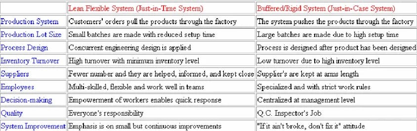
Pitfall 3: Documentation Without Implementation
The mistake: Creating beautiful documents that sit on shelves while operations continue unchanged.
The solution: Implement processes first, document second. Ensure training and adherence. Regular audits should verify actual practice, not just document existence.

Pitfall 4: Treating Certification as the Goal
The mistake: Focusing on passing the audit rather than building a quality culture.
The solution: View certification (if pursued) as validation of effective practices, not the endpoint. Focus on continuous improvement and business results.
Pitfall 5: Inadequate Training
The mistake: Assuming employees understand new processes without proper training.
The solution: Invest in comprehensive training. Verify understanding. Provide ongoing coaching and support.
Pitfall 6: Neglecting Customer Focus
The mistake: Focusing on internal processes while losing sight of customer needs.
The solution: Build customer feedback into your QMS. Regularly review customer satisfaction. Ensure processes ultimately serve customer requirements.
FAQ: Job Shop Manufacturing and ISO 9001 QMS
1. What is job shop manufacturing in simple terms?
Job shop manufacturing refers to a production environment focused on custom, low-volume work where each job may have unique specifications, processes, and routing. Unlike mass production, job shops prioritize flexibility and adaptability to meet diverse customer requirements.
2. Why is ISO 9001 important for job shop manufacturers?
ISO 9001 provides a structured framework to ensure consistent quality, improve processes, and build customer trust. For job shops, it helps manage complexity, reduce variability, and meet the strict requirements of industries such as automotive, aerospace, and industrial manufacturing.
3. Can ISO 9001 work in a high-mix, low-volume environment?
Yes, when it is implemented correctly. Instead of rigid, production-style systems, job shops should adopt a flexible QMS structure that separates general procedures from job-specific work instructions. This approach maintains control while allowing operational agility.
4. What are the biggest challenges of implementing ISO 9001 in a job shop?
Common challenges include:
- High variability in processes and routing
- Increased documentation requirements for each job
- Complex planning and scheduling
- Managing diverse customer specifications
A tailored, risk-based approach is essential to overcome these challenges effectively.
5. How long does it take to implement ISO 9001 in a job shop?
Most job shops require approximately 6–12 months for full implementation, depending on current process maturity, resource availability, and whether certification is pursued.
6. What documents are required for ISO 9001 in job shop manufacturing?
Key documents typically include:
- Quality policy and objectives
- Process procedures (quoting, planning, purchasing, inspection)
- Job-specific work instructions
- Inspection and quality records
- Corrective action and audit records
The goal is to keep documentation practical, usable, and aligned with real operations.
7. How does ISO 9001 improve customer satisfaction?
ISO 9001 improves customer satisfaction by:
- Ensuring consistent product quality
- Reducing defects and rework
- Improving on-time delivery
- Creating clear communication and requirement review processes
This leads to stronger long-term customer relationships.
8. Is ISO 9001 certification required to win manufacturing contracts?
In many industries, especially automotive, aerospace, and medical, ISO 9001 certification is either required or strongly expected. Even in general industrial sectors, it significantly enhances credibility and competitiveness.
9. How does ISO 9001 support sourcing and manufacturing in Southeast Asia?
ISO 9001 provides international quality assurance, making it easier for global buyers to trust suppliers across regions. This is particularly important for companies involved in forging in Vietnam, where buyers expect strong documentation, traceability, and consistent process control.
10. What is the key to a successful ISO 9001 implementation in a job shop?
The most important factor is designing a system that fits your operations, not forcing your operations to fit a rigid system. A successful QMS should be:
- Practical and easy to use
- Flexible for different jobs
- Focused on real process improvement
- Supported by leadership and employees
Conclusion: Building a QMS That Works for Your Job Shop
Implementing ISO 9001 in a job shop manufacturing environment presents unique challenges, but also unique opportunities. The key is designing a quality management system that:
1. Acknowledges job shop variability rather than fighting it
2. Provides flexible frameworks that adapt to diverse jobs
3. Focuses on practical value rather than bureaucratic compliance
4. Engages employees in quality improvement
5. Drives continuous improvement in both quality and efficiency
6. Serves customer needs consistently despite operational complexity
The step-by-step approach outlined in this guide, leadership commitment, gap analysis, documentation design, process controls, measurement systems, certification preparation, and ongoing maintenance, provides a roadmap for successful implementation.
Remember: The goal is not a perfect QMS on paper, but a quality management system that improves your ability to deliver excellent custom manufacturing to your customers, including in competitive sectors such as Forging Vietnam. Start with that principle, and build a system that serves your business rather than burdening it.
With thoughtful implementation tailored to job shop realities, ISO 9001 becomes not a constraint but a competitive advantage that enables you to demonstrate capability, win new business, reduce costs, and continuously improve in the dynamic world of custom manufacturing, particularly within the Forging industry in Vietnam.
About Align Manufacturing
Align Manufacturing provides precision CNC machining and fabrication services with ISO 9001-certified quality management systems. We specialize in custom components for automotive, aerospace, medical, and industrial applications.
Related Resources:
- [A Complete Guide to Sourcing Forged Components from Vietnam](https://alignmfg.co/a-complete-guide-to-sourcing-forged-components-from-vietnam/)
- [How to Choose the Right Fabrication Partner in Vietnam](https://alignmfg.co/how-to-choose-the-right-fabrication-partner-in-vietnam/)
- [Forged vs Cast: What’s the Real Difference](https://alignmfg.co/forged-vs-cast-whats-the-real-difference-in-strength-and-cost/)
Brass vs. Bronze: A Manufacturing Guide for Material Selection
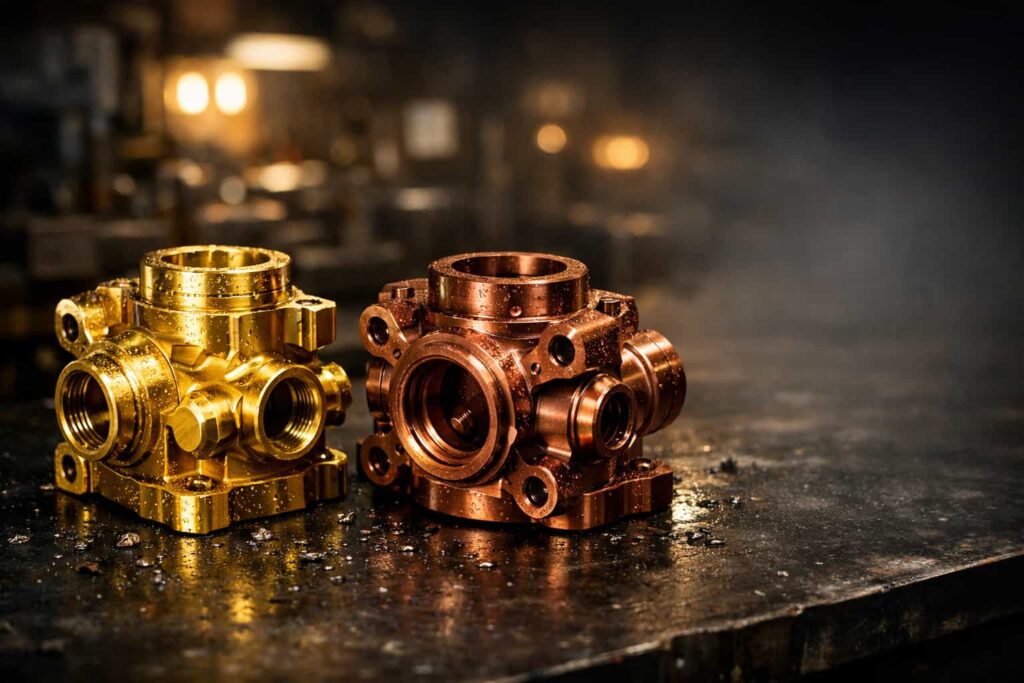
Introduction: Understanding the Confusion
Brass and bronze, copper alloys that share a similar golden appearance and are frequently confused even by experienced engineers and buyers. Both have served humanity for millennia, both machine beautifully, both resist corrosion, yet they possess distinctly different properties that make each suitable for specific applications.
For manufacturers, specifying the wrong alloy can result in premature failure, increased costs, or dissatisfied customers. This comprehensive guide provides the metallurgical knowledge and practical guidance needed to select confidently between brass and bronze for your components.
Composition: The Fundamental Difference
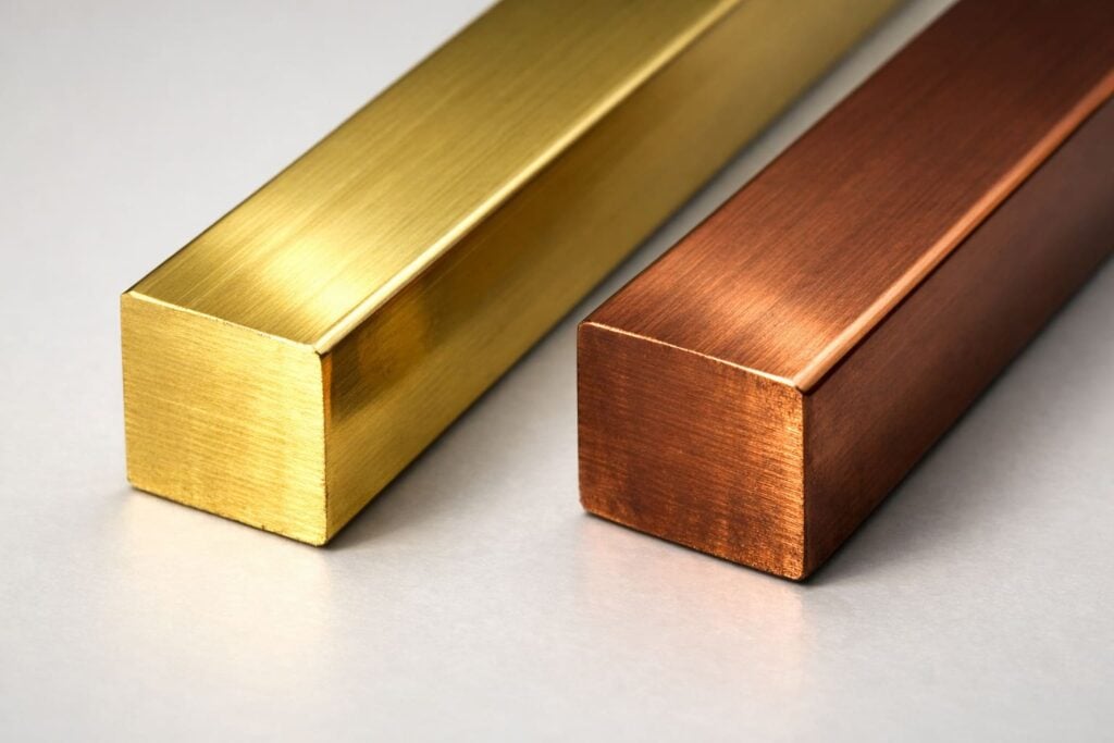
Brass: Copper + Zinc
Primary Alloying Element: Zinc (Zn)
Copper Content: Typically 55-85%
Key Characteristics:
- Excellent machinability (especially with lead additions)
- Good cold workability
- Color ranges from reddish (high copper) to yellow-gold (lower copper)
- Lower material cost than bronze
Common Brass Alloys
| Alloy | UNS | Cu % | Zn % | Other | Primary Application |
| Red Brass | C23000 | 85 | 15 | — | Plumbing, hardware |
| Cartridge Brass | C26000 | 70 | 30 | — | Deep drawing, ammunition |
| Yellow Brass | C27000 | 65 | 35 | — | General hardware |
| Free-Cutting | C36000 | 61.5 | 35.5 | 3% Pb | Machined components |
| Forging Brass | C37700 | 58-61 | 39-42 | 2% Pb | Hot forged parts |
| Naval Brass | C46400 | 60 | 39.25 | 0.75% Sn | Marine applications |
Bronze: Copper + (Tin, Aluminum, Silicon, or Other)
Primary Alloying Elements: Tin (Sn), Aluminum (Al), Silicon (Si), Nickel (Ni), or Phosphorus (P)
Copper Content: Typically 80-95%
Key Characteristics:
- Generally stronger than brass
- Superior wear resistance
- Excellent corrosion resistance (especially seawater)
- No zinc-related dezincification concerns
- Higher material cost
Common Bronze Alloys
| Alloy | UNS | Cu % | Primary Alloying | Key Properties |
| Tin Bronze | C90500 | 88 | 10% Sn | Traditional bronze, excellent castability |
| Aluminum Bronze | C95400 | 83 | 11% Al, 4% Fe | High strength, wear resistance |
| Silicon Bronze | C65500 | 97 | 3% Si | Good strength, weldability |
| Phosphor Bronze | C51000 | 95 | 5% Sn, 0.2% P | Springs, electrical contacts |
| Manganese Bronze | C86300 | 63 | 25% Zn, 6% Al | High strength, bearing properties |
| Nickel Aluminum Bronze | C63000 | 82 | 10% Al, 5% Ni | Premium marine alloy |
Comparative Properties Analysis
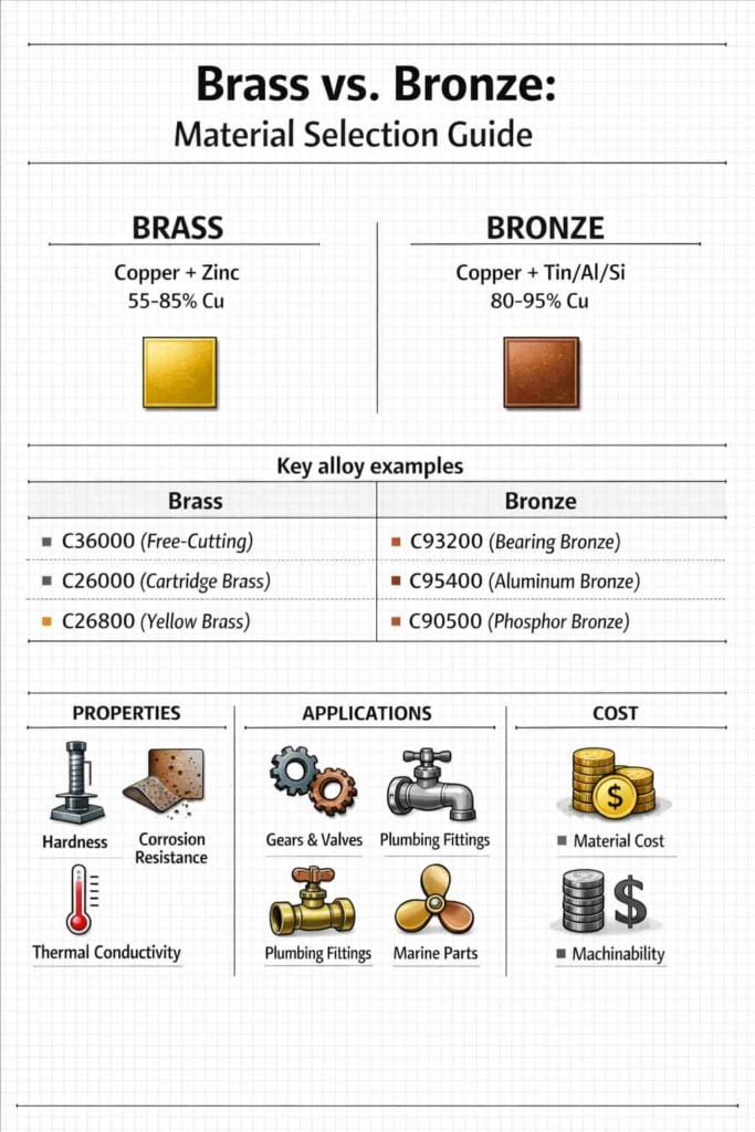
Mechanical Properties
| Property | Brass (C36000) | Bronze (C90500) | Bronze (C95400) | Winner |
| Tensile Strength | 58,000 PSI | 45,000 PSI | 85,000 PSI | Bronze (Al) |
| Yield Strength | 45,000 PSI | 22,000 PSI | 35,000 PSI | Brass |
| Hardness (HB) | 85 | 75 | 170 | Bronze (Al) |
| Elongation | 25% | 20% | 12% | Brass |
| Fatigue Strength | 20,000 PSI | 15,000 PSI | 28,000 PSI | Bronze (Al) |
| Machinability | 100% (standard) | 40% | 50% | Brass |
Note: Properties vary significantly by specific alloy and temper.
Corrosion Resistance
Fresh Water
- Both brass and bronze perform excellently
- Brass C23000 and C26000 preferred for plumbing
- Bronze unnecessary cost for most fresh water
Seawater
- Bronze significantly outperforms brass
- Aluminum bronze and nickel-aluminum bronze standard for marine
- Brass subject to dezincification in seawater
- Naval brass (C46400) acceptable for limited marine exposure
Chemical Environments
| Environment | Brass Performance | Bronze Performance | Recommendation |
| Acids (dilute) | Poor | Fair | Neither ideal |
| Alkalis | Good | Good | Either acceptable |
| Chlorides | Moderate (risk dezincification) | Excellent | Bronze |
| Ammonia | Poor (SCC risk) | Poor (SCC risk) | Avoid both |
| Oxidizing acids | Poor | Poor | Neither |
| Non-oxidizing acids | Moderate | Good | Bronze preferred |
Wear Characteristics
Galling Resistance
- Bronze alloys generally superior to brass
- Aluminum bronze excellent against steel
- Tin bronze good for bearing applications
Bearing Properties
| Application | Recommended Alloy | Why |
| Light loads, oil lubricated | C93200 (SAE 660) | Standard bearing bronze |
| Heavy loads, slow speed | C95400 | High strength, embeddability |
| Marine propellers | C95800 | Cavitation resistance |
| Pivot bushings | C86300 | Manganese bronze, durable |
| Food equipment | C54400 | Lead-free phosphor bronze |
Manufacturing Process Considerations
Machinability Comparison
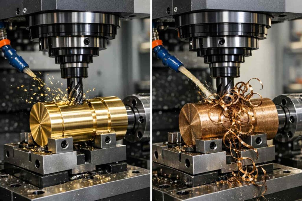
Brass Machinability Advantages
- C36000 is the machinability standard (rated 100%)
- Free-machining grades produce small, broken chips
- Minimal tool wear
- Excellent surface finish achievable
- High cutting speeds possible
Bronze Machining Considerations
- Generally 30-50% machinability of brass
- Long, stringy chips (especially tin bronzes)
- Higher cutting forces required
- More frequent tool changes
- Lower surface speeds recommended
Machining Parameter Recommendations
| Parameter | Free-Cutting Brass (C36000) | Aluminum Bronze (C95400) |
| Cutting Speed (SFM) | 300-800 | 150-300 |
| Feed Rate (IPR) | 0.005-0.015 | 0.003-0.010 |
| Depth of Cut | Full depth possible | Conservative recommended |
| Tool Material | HSS or Carbide | Carbide preferred |
| Coolant | Optional | Required |
Casting Characteristics
Brass Casting
- Excellent fluidity
- Lower pouring temperatures (1,650-1,850°F)
- Good for intricate shapes
- Sand, investment, and die casting all suitable
- Lower energy costs
Bronze Casting
- Tin bronzes: Excellent castability, used for statuary and bearings
- Aluminum bronzes: Higher pouring temps (2,000-2,200°F)
- More prone to oxidation during pouring
- Excellent for heavy-section castings
- Sand and investment casting preferred
Casting Process Selection
| Volume | Brass Method | Bronze Method |
| Prototype (1-10) | Sand or investment | Sand or investment |
| Low (10-100) | Sand | Sand |
| Medium (100-10,000) | Permanent mold | Investment |
| High (10,000+) | Die casting | Centrifugal (for bearings) |
Forging and Forming
Brass
- Excellent hot and cold forgeability
- C37700 specifically designed for hot forging
- Cold heading common for fasteners and fittings
- Deep drawing capability (cartridge cases, cups)
Bronze
- Hot forging preferred
- Cold work limited (work hardens rapidly)
- Silicon bronze (C65500) has best formability
- Aluminum bronze requires high forging temperatures
Joining Methods
Soldering and Brazing
- Both solder and braze well with appropriate fluxes
- Bronze requires higher brazing temperatures
- Careful joint design for dissimilar metal joining
Welding
| Alloy | Weldability | Method |
| C36000 (Brass) | Fair | Gas, TIG (zinc fuming issues) |
| C23000 (Brass) | Good | Gas, TIG |
| C51000 (Phos. Bronze) | Excellent | TIG, resistance |
| C65500 (Silicon Bronze) | Excellent | TIG, MIG (gas metal arc) |
| C95400 (Alum. Bronze) | Good | TIG with DCEP |
Cost Analysis
Material Costs (Approximate, 2026)
| Alloy | Form | Cost per lb (USD) | Relative Cost |
| C36000 (Brass) | Rod/bar | $3.50-4.50 | 1.0× (baseline) |
| C26000 (Brass) | Sheet | $3.00-4.00 | 0.9× |
| C83600 (Red Brass) | Ingot | $3.75-4.75 | 1.1× |
| C90500 (Tin Bronze) | Ingot | $4.50-6.00 | 1.4× |
| C93200 (Bearing Bronze) | Bar | $5.00-7.00 | 1.5× |
| C95400 (Alum. Bronze) | Bar | $6.00-8.50 | 1.8× |
| C63000 (Ni-Al Bronze) | Bar | $8.00-12.00 | 2.5× |
| C65500 (Silicon Bronze) | Wire | $4.50-6.50 | 1.4× |
Total Cost of Ownership
Factor brass advantages:
- Lower material cost
- Higher machining speeds (lower labor cost)
- Less tool wear
- Faster production times
Factor bronze advantages:
- Longer service life in aggressive environments
- Reduced maintenance/replacement costs
- No dezincification failure risk
- Better wear properties (longer bearing life)
Break-Even Analysis Example: Marine Valve Handle
| Factor | Brass (C46400) | Bronze (C95400) |
| Material cost | $4.00 | $7.00 |
| Machining time | 15 min | 25 min |
| Tool cost | $2.00 | $5.00 |
| Unit cost | $20 | $35 |
| Service life (seawater) | 5 years | 20+ years |
| 20-year cost | $80 (4 replacements) | $35 |
Bronze is clearly the economic choice for long-term marine applications despite higher initial cost.
Application-Specific Selection Guide
Plumbing and Fluid Handling
| Component | Recommended | Rationale |
| Potable water valves | C23000, C26000 brass | Cost, NSF/ANSI 61 compliance |
| Seawater valves | C95800, C63000 bronze | Corrosion resistance |
| Steam fittings | C83600 brass, C92200 bronze | Heat resistance |
| Sanitary fittings | C36000 (lead-free), C54400 bronze | Machinability, no lead |
| Pressure vessels | C83600 brass, C95400 bronze | Strength requirements |
Electrical Applications
| Component | Recommended | Rationale |
| Terminals | C36000 brass | Conductivity, machinability |
| Springs/contacts | C51000 phosphor bronze | Elasticity, fatigue resistance |
| Busbars | C11000 copper (pure) | Maximum conductivity |
| Connectors | C26000 brass | Formability, cost |
| Switches | C54400 phosphor bronze | Wear resistance |
Marine and Offshore
| Component | Recommended | Rationale |
| Propellers | C95800 nickel-aluminum bronze | Cavitation resistance |
| Seawater pumps | C95500 aluminum bronze | Corrosion, erosion resistance |
| Valve bodies | C95800, C63000 | Pressure, corrosion resistance |
| Fasteners | C65500 silicon bronze | Strength, galvanic compatibility |
| Heat exchangers | C68700 aluminum brass | Heat transfer, cost balance |
Decorative and Architectural
| Application | Recommended | Rationale |
| Door hardware | C26000, C27000 brass | Color, formability |
| Statuary | C90500 tin bronze | Traditional appearance, castability |
| Marine hardware | C65500 silicon bronze | Weather resistance |
| Furniture | C23000 brass | Color, workability |
| Fasteners (exterior) | C65500 silicon bronze | No rust, no staining |
Industrial Machinery
| Component | Recommended | Rationale |
| Bushings/bearings | C93200, C95400 bronze | Wear properties |
| Gears | C95400 aluminum bronze | Strength, wear |
| Worm wheels | C93200 tin bronze | Compatibility with steel worms |
| Valve seats | C83600 brass, C95400 bronze | Machinability, durability |
| Pump impellers | C95500 aluminum bronze | Cavitation resistance |
Common Selection Mistakes
Mistake 1: Specifying Bronze When Brass Is Sufficient
Problem: Unnecessary cost increase of 40-150%
Solution: Evaluate actual service conditions. If:
- Not exposed to seawater
- No heavy bearing loads
- No severe wear conditions
- Brass likely sufficient
Mistake 2: Using High-Zinc Brass in Marine Environments
Problem: Rapid dezincification failure
Solution:
- Specify aluminum bronze or nickel-aluminum bronze for seawater
- If brass required, use C46400 naval brass maximum
- Consider cathodic protection systems
Mistake 3: Ignoring Machinability in High-Volume Production
Problem: Increased cycle times, tool costs, rejects
Solution:
- For high-volume machined parts, specify free-machining brass (C36000) if properties permit
- Consider near-net-shape casting for bronze components to minimize machining
- Calculate total cost including machining
Mistake 4: Mixing Brass and Bronze in Assemblies
Problem: Galvanic corrosion potential
Solution:
- Generally compatible (both copper alloys)
- Minor galvanic potential difference
- In seawater, bronze should be more noble component
- Use dielectric isolation if concerned
Mistake 5: Specifying by Color Only
Problem: Brass and bronze can appear similar; composition determines performance
Solution:
- Always specify by UNS alloy number
- Require material certifications
- Verify incoming material with XRF or similar
Southeast Asia Manufacturing Context
Regional Availability
Thailand
- Extensive brass availability (C23000-C37700)
- Bronze selection limited, especially specialty alloys
- Aluminum bronze and phosphor bronze available from distributors
- Nickel-aluminum bronze typically imported
China
- Full range of brass and bronze alloys available
- C95400, C95800 produced domestically
- Cost advantages for both materials
- Quality varies when sourcing from certified mills
Japan/Korea
- Highest quality alloys available
- Premium pricing
- Excellent for aerospace and medical applications
Export Considerations
US Market
- NSF/ANSI 61 for potable water contact
- NSF/ANSI 372 lead content requirements
- RoHS compliance for electronics
European Market
- REACH compliance
- EN material standards may differ from ASTM
- CE marking requirements for certain applications.
Conclusion
Choosing between brass and bronze is ultimately about matching material performance to the real demands of the application. Brass may be the better fit where machinability, cost efficiency, and high-volume production matter most, while bronze becomes the stronger choice for harsher environments that demand superior wear and corrosion resistance. At Align Mfg, we help customers make that decision with confidence by combining technical material knowledge with practical manufacturing experience, ensuring every component is selected not just for price or appearance, but for long-term performance and production efficiency. As a company with expertise in thailand precision machining, we understand how the right alloy choice directly impacts machining quality, service life, and total project cost.
For engineers, buyers, and product developers, the difference between brass and bronze should never be reduced to colour alone. Successful material selection depends on application conditions, expected lifespan, manufacturability, and downstream performance in the field. Align Mfg supports this process with a manufacturing-first approach, helping clients turn material specifications into reliable, production-ready parts that meet demanding industrial standards. Whether the requirement is for corrosion resistance, strength, or precision-machined consistency, our team works to deliver solutions that are both technically sound and commercially practical.
FAQ
Q1: Can you distinguish brass from bronze visually?
A: Sometimes, but not reliably:
- Color: High-copper brass (C23000) is reddish like bronze; low-copper brass (C28000) is distinctly yellow. Tin bronze tends toward reddish-brown; aluminum bronze more golden.
- Sound: Bronze rings with clearer tone; brass slightly duller.
- Certain identification: Requires chemical analysis (XRF) or spark test by experienced metallurgist.
Q2: Why is bronze more expensive than brass?
A: Several factors:
- Raw materials: Tin more expensive than zinc; aluminum bronze requires high-purity aluminum
- Processing: Higher melting temperatures increase energy costs
- Volume: Brass produced in much larger quantities (economies of scale)
- Applications: Bronze often specified for critical/long-life applications, commanding premium
Q3: Can bronze be machined as easily as brass?
A: Generally no. Free-cutting brass (C36000) is the machinability standard. Most bronzes machine at 30-50% that speed. Exceptions:
- C54400 (lead-free phosphor bronze) machines reasonably well
- C65500 (silicon bronze) is machinable but work-hardens
- Tin bronzes produce stringy chips requiring management
Q4: Is bronze always stronger than brass?
A: Generally yes, but with exceptions:
- Cold-worked brass (H04 temper) can exceed cast bronze strength
- Aluminum bronzes (C95400, C63000) are significantly stronger than any brass
- Bearing bronzes (C93200) prioritize lubricity over strength
- Always compare specific alloys and tempers
Q5: Will brass and bronze corrode if used together?
A: Minimal galvanic concern:
- Both are copper alloys with similar electrode potentials
- In most environments, no significant galvanic corrosion
- In seawater, bronze is slightly more noble—brass would corrode preferentially if any
- Best practice: Use same alloy or bronze for more critical component
Q6: Can I substitute brass for bronze in a bearing application?
A: Generally not advisable:
- Bronze bearings designed for embeddability (dirt embeds without scoring shaft)
- Brass lacks tin content that provides lubricity
- Bronze bearing alloys formulated for specific wear properties
- Emergency short-term: possible; long-term: expect premature failure
Q7: What’s the best alloy for saltwater exposure?
A: For continuous seawater immersion:
- C95800 (Nickel-Aluminum Bronze) – Best overall
- C95500 (Aluminum Bronze) – Good, less expensive
- C63000 (Nickel-Aluminum Bronze) – High strength
For occasional salt spray:
- C46400 (Naval Brass) acceptable
- C65500 (Silicon Bronze) good corrosion resistance
Q8: How do I specify material to avoid receiving the wrong alloy?
A: Best practices:
- Specify UNS number (e.g., “C36000 per ASTM B16”) not just “brass”
- Require material certification with chemical composition
- Verify incoming material with XRF gun or lab analysis for critical applications
- Use qualified suppliers with material traceability systems
- Include acceptance testing in purchase agreements
Brass Valve Manufacturing: Forging vs. Casting for Durability & Pressure
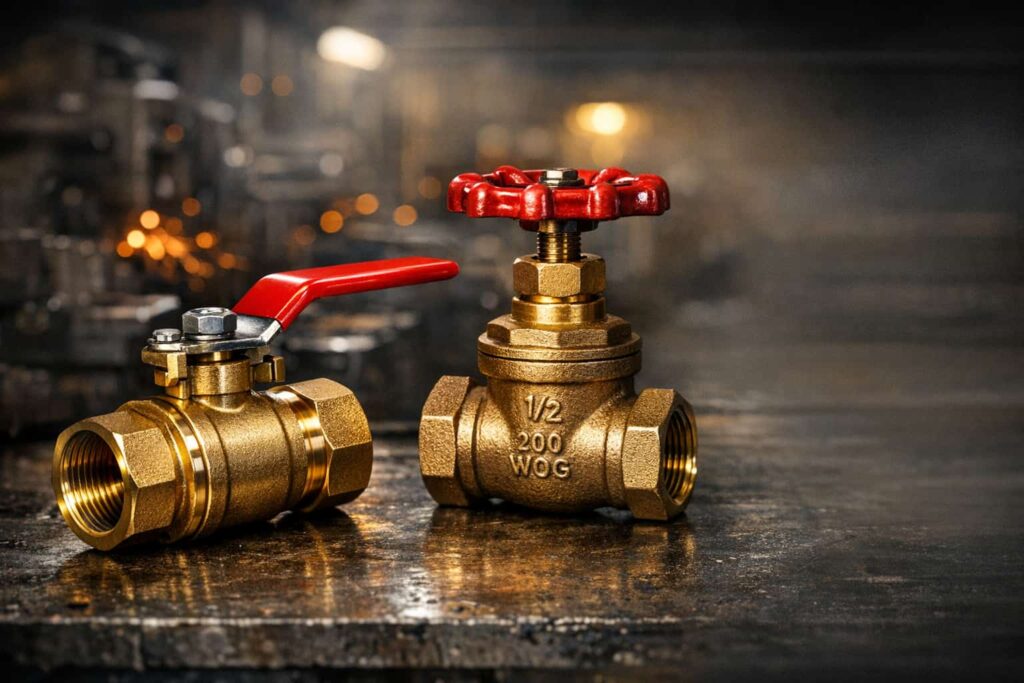
Introduction: The Critical Choice in Valve Production
Brass valves are essential components in plumbing, industrial, and marine applications where reliable fluid control under pressure is non-negotiable. The manufacturing method, forging versus casting, fundamentally determines the valve’s mechanical properties, pressure ratings, durability, and cost. Understanding these differences enables buyers and engineers to make informed decisions that balance performance requirements with budget constraints.
This technical deep-dive compares forging and casting processes for brass valve manufacturing, examining how each method affects material structure, pressure handling, longevity, and economic considerations.
Understanding Brass Valve Applications
Common Valve Types
| Valve Type | Primary Application | Pressure Requirements | Typical Manufacturing Method |
| Ball Valves | On/off flow control | 150-600 PSI WOG | Both forging and casting |
| Gate Valves | Isolation services | 125-250 PSI | Primarily casting |
| Globe Valves | Throttling applications | 150-300 PSI | Forging preferred |
| Check Valves | Backflow prevention | 200-600 PSI | Both methods |
| Pressure Relief Valves | Safety applications | 50-400 PSI set pressure | Forging required |
| Marine Valves | Seawater applications | 150-300 PSI | Forging with DZR brass |
Industry Standards
Brass valves must comply with multiple standards depending on application:
- ASTM B62: Standard specification for composition bronze or ounce metal castings
- ASTM B16/B16M: Free-cutting brass rod, bar and shapes for use in screw machines
- NSF/ANSI 61: Drinking water system components, health effects
- NSF/ANSI 372: Drinking water system components, lead content
- MSS SP-110: Ball valves threaded, socket-welding, solder joint, grooved and flared ends
- UL 252: Compressed gas pressure regulators
Forging: The Strength Advantage
The Forging Process for Brass Valves
Forging shapes brass by applying compressive force to heated billets or bar stock. The process fundamentally transforms the material’s internal structure:
- Billet Preparation: Brass rod or bar (typically C36000 free-cutting brass or C37700 forging brass) is cut to weight
- Heating: Billets heated to 1,200-1,400°F (650-760°C) for optimal plasticity
- Forming: Mechanical presses (up to 2,500 tons) or hammers shape the heated brass into valve bodies
- Trimming: Excess material (flash) is removed
- Heat Treatment: Stress relief annealing for complex geometries
- Machining: Precision CNC finishing of seats, threads, and sealing surfaces
Metallurgical Benefits of Forging
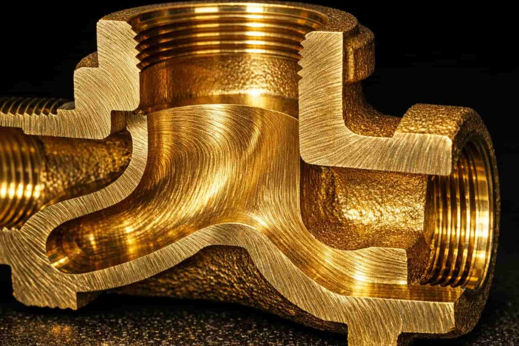
Grain Structure Alignment Forging creates directional grain flow that follows the valve’s contours. This grain alignment provides:
- Superior fatigue resistance (3-5× better than castings)
- Higher impact strength
- Improved resistance to stress corrosion cracking
Porosity Elimination Unlike casting, forging eliminates internal porosity through compression:
- Zero gas porosity or shrinkage cavities
- Uniform density throughout the valve body
- Predictable pressure ratings without weak points
Mechanical Property Improvements
| Property | Forged Brass | Cast Brass | Improvement |
| Tensile Strength | 50,000-60,000 PSI | 30,000-40,000 PSI | +50-67% |
| Yield Strength | 35,000-45,000 PSI | 15,000-20,000 PSI | +100-125% |
| Elongation | 15-25% | 15-20% | Similar |
| Fatigue Strength | 18,000-22,000 PSI | 6,000-10,000 PSI | +120-200% |
| Hardness (Brinell) | 80-100 HB | 60-80 HB | +25-33% |
Pressure Rating Advantages
Forged brass valves consistently achieve higher working pressure ratings:
- Standard Forged Valves: 600 PSI WOG (Water, Oil, Gas)
- High-Pressure Forged: 1,500+ PSI for hydraulic applications
- Steam Service: 250 PSI saturated steam ratings common
The absence of internal defects means forged valves can safely handle pressure spikes and thermal cycling that would risk casting failure.
When Forging is Essential
Specify forged brass valves for:
- High-pressure applications (>300 PSI)
- Thermal cycling environments
- Safety-critical systems (gas, steam)
- Corrosive media (saltwater, chemicals)
- Applications requiring maximum longevity
- Aerospace and military specifications
Casting: The Economic and Geometric Advantage
Casting Processes for Brass Valves
Multiple casting methods produce brass valve bodies, each with distinct characteristics:
Sand Casting
- Traditional method using bonded sand molds
- Suitable for large valves (>2 inches)
- Lower tooling costs, rougher surface finish
- Requires more machining allowance
Investment Casting (Lost Wax)
- Wax patterns coated with ceramic shell
- Excellent for complex internal geometries
- Near-net-shape reduces machining
- Best surface finish of casting methods
Die Casting
- High-pressure injection into steel dies
- Fast cycle times for high volumes
- Excellent dimensional repeatability
- Limited to zinc-based alloys primarily
Permanent Mold Casting
- Gravity-fed into reusable metal molds
- Good mechanical properties
- Cost-effective for medium volumes
- Common for 1/2″ to 3″ valve sizes
Economic Advantages of Casting
Lower Material Waste
- Near-net-shape reduces machining by 30-50%
- Complex internal passages cast-in, not machined
- Recycled gating and riser material
Tooling Amortization
- Sand casting: Lowest tooling cost ($5,000-$20,000)
- Investment casting: Moderate cost ($15,000-$50,000)
- Permanent mold: Higher cost ($25,000-$100,000) but long life
Volume Economics
| Volume (units/year) | Most Economical Method |
| <1,000 | Sand casting |
| 1,000-10,000 | Investment casting |
| 10,000-50,000 | Permanent mold |
| >50,000 | Die casting (if alloy permits) |
Geometric Flexibility
Casting enables features impossible or prohibitively expensive to forge:
- Complex internal flow passages
- Integral mounting flanges
- Thin-walled sections (down to 1/8″)
- Irregular external shapes
- Multiple cavity configurations
Casting Quality Considerations
Porosity Management
- Proper gating and riser design essential
- Vacuum-assisted casting reduces gas porosity
- Hot isostatic pressing (HIP) can heal internal defects (adds cost)
Wall Thickness Guidelines
- Minimum: 1/8″ (3mm) for small castings
- Recommended: 3/16″ to 1/4″ for pressure retention
- Thick sections (>1/2″) risk shrinkage porosity
Comparative Analysis: Forging vs. Casting
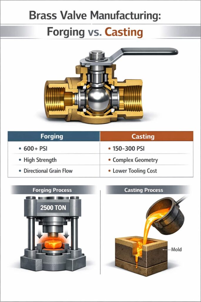
Performance Comparison
| Criteria | Forging | Casting | Winner |
| Pressure Rating | 600+ PSI | 150-300 PSI | Forging |
| Fatigue Life | Excellent | Good | Forging |
| Impact Resistance | Excellent | Moderate | Forging |
| Corrosion Resistance | Better (uniform structure) | Good | Forging |
| Complex Geometry | Limited | Excellent | Casting |
| Internal Passages | Machined only | Cast-in | Casting |
| Surface Finish | Machined surfaces excellent | As-cast surfaces rougher | Forging |
| Dimensional Tolerance | ±0.005″ | ±0.010-0.030″ | Forging |
| Material Utilization | 40-60% | 70-85% | Casting |
| Production Rate | Moderate | High (permanent mold/die) | Casting |
| Tooling Cost | High ($50K-$200K) | Low to Moderate ($5K-$100K) | Casting |
| Unit Cost (low volume) | Higher | Lower | Casting |
| Unit Cost (high volume) | Lower | Higher | Forging |
Cost Analysis at Different Volumes
Scenario: 2-inch brass ball valve
| Volume | Forged Cost | Cast Cost | Difference |
| 100 units | $85/unit | $45/unit | Casting -47% |
| 1,000 units | $42/unit | $32/unit | Casting -24% |
| 10,000 units | $28/unit | $26/unit | Casting -7% |
| 50,000 units | $18/unit | $24/unit | Forging +25% |
Note: Costs include amortized tooling and assume standard C36000 forged brass vs. C84400 cast brass.
Southeast Asia Manufacturing Considerations
Regional Capabilities
Thailand
- Strong forging base with Japanese investment
- C36000 and C37700 brass readily available
- IATF 16949 certified suppliers for automotive valves
- Competitive for 10,000+ unit volumes
China
- Largest global casting capacity
- Sand and investment casting expertise
- Wide range of brass alloys available
- Lowest cost for high volumes (>50,000)
Vietnam
- Growing casting industry
- Cost-competitive for medium volumes
- Improving quality systems
- Good for 5,000-30,000 unit ranges
Quality Assurance Recommendations
When sourcing from Southeast Asia:
- Specify Material Grade: Require mill test certificates for C36000 (forged) or C83600/C84400 (cast)
- Hydrostatic Testing: 100% testing at 1.5× working pressure minimum
- Dimensional Inspection: CMM verification of critical sealing surfaces
- Metallurgical Verification: Grain structure analysis for forgings; porosity testing for castings
- Third-Party Inspection: Engage SGS, Bureau Veritas, or similar for critical applications
Selection Guide: When to Choose Each Method
Choose Forging When:
✓ Working pressure exceeds 300 PSI
✓ Application involves thermal cycling
✓ Safety-critical (gas, steam, hazardous fluids)
✓ Long service life required (>20 years)
✓ High fatigue loading (frequent operation)
✓ Corrosive environment (seawater, chemicals)
✓ Volume exceeds 25,000 units annually
✓ Aerospace, military, or nuclear specifications
Choose Casting When:
✓ Working pressure under 200 PSI
✓ Complex internal geometry required
✓ Weight minimization critical
✓ Volume under 10,000 units annually
✓ Budget constraints significant
✓ Large diameter valves (>3 inches)
✓ Non-critical applications (irrigation, drainage)
✓ Prototyping or product development phase
FAQ
Q1: Can you visually tell the difference between forged and cast brass valves?
A: Sometimes. Forged valves typically have visible parting lines from the forging dies and uniform, machined surfaces. Cast valves may show mold parting lines, slight surface roughness on as-cast areas, and occasionally visible porosity on cut sections. However, finished valves with full machining can be difficult to distinguish visually, material testing (spectroscopy, metallography) provides definitive identification.
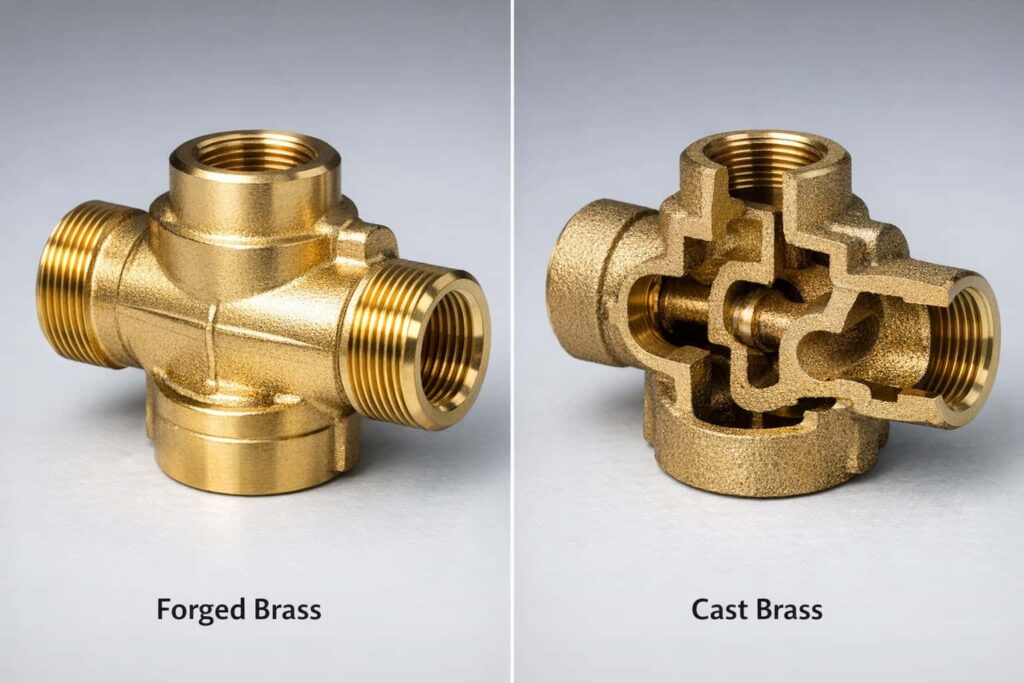
Q2: Why do forged valves cost more for small quantities?
A: Forging requires dedicated dies (typically $50,000-$200,000) and larger press equipment. The high fixed costs must be amortized over production volume. Casting, particularly sand casting, has lower tooling costs ($5,000-$20,000), making it more economical for prototypes and low volumes despite higher per-unit material and labor costs.
Q3: Are forged valves always better than cast valves?
A: Not necessarily. Forged valves offer superior mechanical properties and pressure ratings, but casting provides geometric flexibility and cost advantages for appropriate applications. A properly designed and manufactured cast valve performing within its rated pressure range is perfectly suitable for many applications. The “best” valve depends on the specific service conditions, longevity requirements, and budget constraints.
Q4: Can cast brass valves handle high pressure if they’re thick enough?
A: Wall thickness helps, but doesn’t eliminate casting defects. Thick sections in castings actually increase the risk of shrinkage porosity, which becomes stress concentration points. While heavier cast valves can achieve higher pressure ratings than thin-wall versions, they rarely match forged valve reliability at equivalent pressure levels due to fundamental metallurgical differences in grain structure and defect distribution.
Q5: What’s the lead time difference between forged and cast valves?
A: For existing tooled products, forging typically has shorter lead times (4-8 weeks) compared to sand casting (6-10 weeks) because forging is faster per part. However, for new products, forging requires longer tooling development (12-16 weeks) versus sand casting (4-8 weeks). Investment casting falls between these ranges for both production and tooling.
Q6: Are there brass alloys that can only be forged or only be cast?
A: Yes. C36000 (free-cutting brass) is designed for machining and forging, it’s rarely cast successfully due to lead content affecting fluidity. Conversely, C83600 (red brass) and C84400 (semired brass) are formulated for casting and don’t forge well due to their tin and zinc content affecting hot workability. C37700 (forging brass) and C35300 (high-leaded brass) bridge both processes.
Q7: How do I verify a supplier’s claimed manufacturing method?
A: Request: (1) Material certifications showing alloy grade, (2) Process documentation or PPAP submission, (3) Metallurgical cross-sections showing grain structure (forged shows directional grain flow; cast shows equiaxed grains with potential porosity), (4) Factory audit if volume justifies, (5) Third-party inspection by accredited bodies like SGS or TÜV for critical applications.
Q8: Can you repair a cracked cast valve by welding?
A: Brass welding is challenging and generally not recommended for pressure-containing components. The heat-affected zone creates metallurgical changes that compromise pressure integrity. Minor surface defects can sometimes be repaired by brazing, but cracked valves should be replaced rather than repaired – especially in pressure or safety-critical applications.
Why Brass? The Corrosion Resistance of Brass in Plumbing Systems
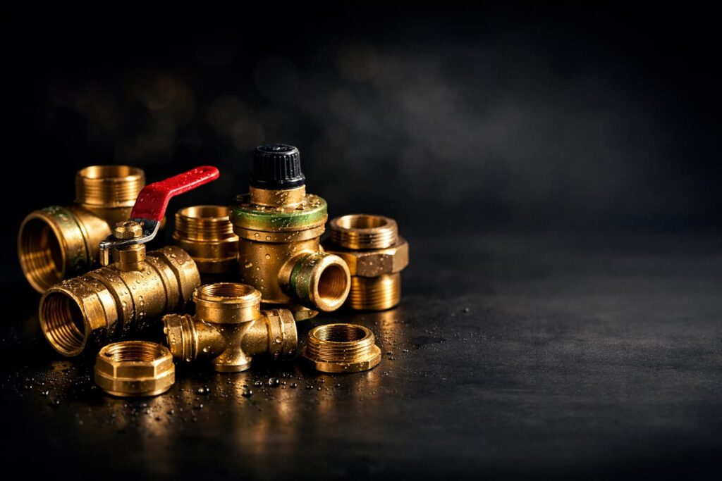
Introduction: The Material Choice That Lasts Generations
Walk through any historic European city and you’ll see brass plumbing fixtures that have functioned for centuries. From ancient Roman aqueducts to modern high-rise buildings, brass has proven itself as the premier material for water handling systems. But why brass? What gives this copper-zinc alloy its remarkable ability to withstand constant water exposure, pressure cycling, and aggressive water chemistries?
This technical exploration examines the metallurgical properties that make brass the material of choice for plumbing systems, diving deep into corrosion mechanisms, alloy selection, and the engineering considerations that guide modern specification.
Understanding Brass: More Than Just Copper and Zinc
Brass Alloy Families
Brass isn’t a single material, it’s a family of alloys with compositions tailored to specific applications:
| Alloy | UNS Designation | Copper % | Zinc % | Lead % | Key Properties |
| Red Brass | C23000 | 85 | 15 | 0 | Excellent corrosion resistance, formability |
| Cartridge Brass | C26000 | 70 | 30 | 0 | Good strength, excellent cold workability |
| Yellow Brass | C27000 | 65 | 35 | 0 | High strength, lower cost |
| Free-Cutting Brass | C36000 | 61.5 | 35.5 | 3 | Machinability, dezincification risk |
| Forging Brass | C37700 | 58-61 | 39-42 | 2-3 | Hot forgeability |
| Admiralty Brass | C44300 | 71 | 28 | 0 + 1% Sn | Superior seawater resistance |
| Aluminum Brass | C68700 | 77 | 20.8 | 0 + 2% Al | High seawater corrosion resistance |
| DZR Brass | C35330 | 62 | 36.8 | <0.1 + As | Dezincification resistant |
How Brass Composition Affects Corrosion Resistance
Copper Content Higher copper content (above 70%) generally improves corrosion resistance:
- Better resistance to dezincification
- Improved pitting resistance
- Superior performance in acidic waters
- Higher material cost
Zinc Content Zinc provides strength but increases susceptibility to certain corrosion mechanisms:
- Each 1% zinc increase raises tensile strength ~1,000 PSI
- Zinc above 35% significantly increases dezincification risk
- High-zinc alloys (>37%) generally not recommended for potable water
Lead Content (Legacy Alloys) Lead was historically added for machinability:
- Lead improves chip breaking during machining
- Lead does not dissolve in brass matrix, exists as discrete particles
- Modern lead-free regulations (NSF/ANSI 372) require <0.25% lead
Corrosion Mechanisms in Water Systems
1. Uniform Corrosion (General Attack)
What Happens The entire surface gradually dissolves into the water, thinning the material uniformly.
Rate Factors
- Water pH (most aggressive at pH <6.5 or >8.5)
- Dissolved oxygen concentration
- Temperature (corrosion rate doubles every 18°F/10°C)
- Water velocity (erosion-corrosion at high flow)
Brass Performance Brass forms a protective patina layer (primarily copper carbonate) that dramatically slows uniform corrosion after initial exposure. In typical potable water:
- Initial corrosion rate: 0.1-0.5 mils/year
- Long-term rate (after patina formation): 0.01-0.05 mils/year
- Expected service life: 50-100+ years
2. Dezincification (Selective Leaching)
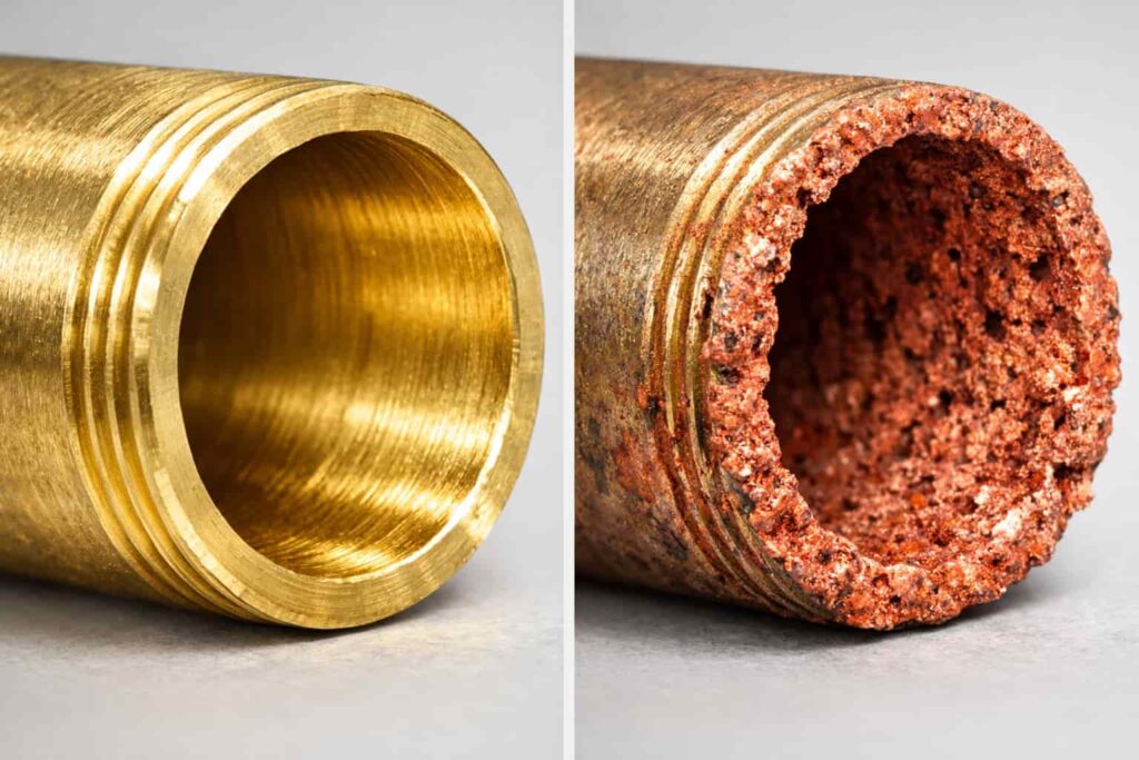
The Mechanism Dezincification is the selective removal of zinc from brass, leaving behind a porous, weak copper structure:
Original brass: Cu-Zn solid solution
↓
Dezincified layer: Porous copper (weak, spongy)
↓
Zn²⁺ ions in water
Two Types of Dezincification
| Type | Appearance | Environment | Rate |
| Plug-type | Localized pits or plugs | Stagnant or low-flow conditions, high chloride, pH >8 | Rapid, destructive |
| Layer-type | Uniform surface layer | High temperature (>140°F), acidic or alkaline pH | Slow, predictable |
Susceptibility by Alloy
- C36000 (61.5% Cu): Highly susceptible
- C37700 (58% Cu): Highly susceptible
- C26000 (70% Cu): Moderately susceptible
- C23000 (85% Cu): Low susceptibility
- DZR Brass (arsenic-inhibited): Resistant
Prevention
- Use low-zinc alloys (>70% Cu) for critical applications
- Specify DZR (dezincification-resistant) brass for aggressive waters
- Limit continuous operating temperature to <140°F (60°C)
- Ensure adequate water velocity to prevent stagnation
3. Pitting Corrosion
The Mechanism Localized attack creating small holes (pits) that can penetrate through walls:
- Initiation at surface inclusions or defects
- Local chemistry changes accelerate attack
- Can cause failure even with minimal weight loss
Factors Promoting Pitting
- Chloride ions (>250 ppm increases risk)
- Sulfate-reducing bacteria
- Carbon dioxide (forms carbonic acid)
- Oxygen concentration cells
- Surface deposits or biofilms
Brass Performance Brass is moderately resistant to pitting. C23000 and C26000 show better pitting resistance than high-zinc alloys. Proper water treatment and periodic system flushing minimize risk.
4. Stress Corrosion Cracking (SCC)
The Mechanism Combination of tensile stress and specific environments causes brittle cracking:
- Tensile stress (residual or applied)
- Ammoniacal environments (ammonia, amines, nitrates)
- Moist atmospheres with industrial pollutants
Symptoms
- Fine cracks visible under magnification
- Often initiates at threads or stress concentrators
- Can occur at stresses below yield strength
Prevention in Brass
- Stress relief annealing after forming/machining
- Avoid contact with ammonia-based cleaners
- Specify stress-relieved material for critical applications
- Design to minimize residual stresses
5. Erosion-Corrosion
The Mechanism Mechanical removal of protective films by high-velocity water, exposing fresh metal to corrosion:
Critical Velocities for Brass
| Water Condition | Maximum Recommended Velocity |
| Clean, treated water | 8-10 ft/sec (2.4-3.0 m/s) |
| Untreated freshwater | 6-8 ft/sec (1.8-2.4 m/s) |
| Seawater | 3-5 ft/sec (0.9-1.5 m/s) |
| Water with particulates | 3-4 ft/sec (0.9-1.2 m/s) |
Mitigation
- Design for lower velocities (larger diameter piping)
- Use erosion-resistant alloys (aluminum brass, 90-10 Cu-Ni)
- Avoid abrupt direction changes and restrictions
- Filter water to remove abrasive particles
Water Chemistry Effects on Brass Corrosion
pH Impact
| pH Range | Effect on Brass | Recommendation |
| <6.0 | Accelerated general corrosion, dezincification risk | Avoid or use C23000/C70600 |
| 6.0-6.5 | Moderate corrosion, manageable with proper alloy | Monitor regularly |
| 6.5-8.5 | Optimal range for most brass alloys | Standard alloys acceptable |
| 8.5-9.0 | Increased dezincification risk | Use DZR or C23000 |
| >9.0 | High dezincification risk, possible SCC | Use C23000 or alternative materials |
Chloride Concentration
Chlorides accelerate localized corrosion:
- <50 ppm: Negligible effect
- 50-250 ppm: Monitor for pitting in hot water systems
- 250-500 ppm: Use C23000 or DZR brass
- >500 ppm: Consider 90-10 Cu-Ni or stainless steel
Hardness and Scale Formation
Paradoxically, moderate water hardness benefits brass:
- Calcium carbonate scale provides barrier protection
- Very soft water (<50 ppm CaCO₃) can be more aggressive
- Very hard water (>300 ppm) may cause flow restriction from scale
Alloy Selection Guide for Plumbing Applications
Potable Water Distribution (Cold)
Recommended Alloys
- C23000 (Red Brass): Best corrosion resistance, higher cost
- C26000 (Cartridge Brass): Good balance of properties and cost
- C27000 (Yellow Brass): Acceptable for non-aggressive waters
- C35330 (DZR): Required for aggressive or unknown water chemistry
Applications
- Valve bodies and components
- Fittings and couplings
- Meter housings
- Backflow preventers
Hot Water Systems
Critical Considerations
- Temperature accelerates dezincification
- Continuous duty above 140°F (60°C) requires special alloys
Recommended Alloys
- C23000 (Red Brass): Preferred for all hot water
- C26000 (Cartridge Brass): Acceptable to 180°F intermittent
- C35330 (DZR): Required for continuous hot water or unknown chemistry
Avoid
- C36000, C37700 in continuous hot water service
- Any high-zinc alloy above 140°F continuous
Seawater and Marine Applications
Aggressive Factors
- High chloride concentration (~19,000 ppm)
- Biological fouling
- Temperature variations
- Velocity effects
Recommended Alloys
- C44300 (Admiralty Brass): Good general purpose marine brass
- C68700 (Aluminum Brass): Superior seawater resistance
- C70600 (90-10 Cu-Ni): Best for high-velocity seawater
Design Guidelines
- Limit velocity to 3-5 ft/sec for brass
- Provide for tube replacement (thin wall designs)
- Consider cathodic protection for severe service
Testing and Standards
Corrosion Test Methods
ASTM B154 – Mercurous Nitrate Test
- Detects susceptibility to stress corrosion cracking
- Specimen exposed to mercurous nitrate solution
- Cracking indicates residual stresses
ISO 6509 – Dezincification Resistance Test
- 24-hour exposure to copper chloride solution at 158°F (75°C)
- Microscopic examination for dezincification depth
- Pass/fail based on allowable penetration
ASTM G48 – Pitting and Crevice Corrosion Resistance
- Ferric chloride exposure test
- Evaluates localized corrosion susceptibility
Material Standards for Plumbing
NSF/ANSI 61 – Drinking Water System Components
- Establishes maximum contaminant levels
- Requires leaching tests for 17-day exposure
- Brass must meet lead content and extraction requirements
NSF/ANSI 372 – Lead Content
- Maximum 0.25% weighted average lead content
- Replaces previous 8% lead content standard
- Requires lead-free alloy formulations
ASTM B16/B16M – Brass Rod, Bar, Shapes
- Specifies C36000 for machining applications
- Material properties and tolerances
Southeast Asia Considerations
Regional Water Chemistry
Thailand Water Supplies
- Bangkok: Moderate hardness (100-150 ppm CaCO₃), pH 7.0-7.5
- Chiang Mai: Softer water, potential for slightly acidic conditions
- Phuket: Variable, coastal areas may have saltwater intrusion
- Industrial areas: Potential for low pH from acid rain
Recommendations
- C26000 acceptable for most applications
- DZR recommended for industrial or unknown water chemistry
- Monitor first installations in new areas for unexpected corrosion
Tropical Climate Effects
High Humidity Storage
- Brass can tarnish rapidly in humid conditions (>70% RH)
- Protective packaging (VCI paper, desiccants) recommended
- Surface oxidation cosmetic only, doesn’t affect performance
Condensation Concerns
- Cold water lines in hot, humid environments sweat
- External condensation can accelerate atmospheric corrosion
- Insulation of cold lines prevents condensation-related issues
Local Standards
Thai Industrial Standards (TIS)
- TIS 2559: Copper and copper alloy tubes for water and gas
- TIS 2560: Fittings for copper tubes
- Generally aligned with ISO and ASTM standards
Conclusion
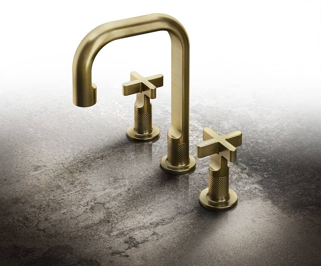
In modern plumbing and industrial systems, the long-term performance of brass is not just a matter of tradition but of precise engineering and material science. From alloy composition to water chemistry, every factor plays a role in ensuring durability, safety, and resistance to corrosion mechanisms such as dezincification and pitting. At Align Mfg, we apply this deep technical understanding to deliver high-quality components through our expertise in thailand precision machining, ensuring that every part meets strict performance standards for demanding environments such as water systems, infrastructure, and industrial applications.
Ultimately, choosing brass is about choosing reliability over decades—not just at installation, but throughout the lifecycle of the system. With the right alloy selection, proper design considerations, and controlled manufacturing processes, brass continues to outperform many alternative materials in both residential and industrial contexts. At Align Mfg, we combine advanced machining capabilities with material expertise to help clients achieve long-lasting, corrosion-resistant solutions that are engineered for real-world conditions.
FAQ
Q1: How long will brass plumbing last?
A: Properly selected and installed brass plumbing typically lasts 50-100 years. Factors affecting longevity:
- Alloy selection (C23000 outlasts C36000 in aggressive water)
- Water chemistry (aggressive water reduces life)
- Temperature (hot water systems age faster)
- Installation quality (excessive strain causes stress corrosion) Many brass fittings from the 1920s-1950s are still in service.
Q2: Why is dezincification such a concern with brass?
A: Dezincification is insidious because:
- It occurs internally, making visual detection difficult
- The remaining porous copper looks normal but has minimal strength
- Failure can be sudden and catastrophic (pipe bursts)
- It’s accelerated by heat, chlorides, and high pH, common in water systems
- Once started, it’s impossible to stop without replacing the affected component
Q3: Can I use standard C36000 brass for potable water?
A: C36000 can be used for potable water but with caveats:
- More susceptible to dezincification than C26000 or C23000
- Requires lead-free formulation (NSF/ANSI 372 compliant)
- Not recommended for continuous hot water service
- Better choice: C26000 for general use, C23000 for critical/aggressive applications
Q4: What’s the difference between “lead-free” and “no-lead” brass?
A: Under NSF/ANSI 372:
- Lead-free: Maximum 0.25% weighted average lead content
- No-lead: Marketing term, same 0.25% requirement
- Biocide brasses (C69300, C87850) use silicon or bismuth instead of lead for machinability
- All brasses labeled for potable water in the US must meet NSF/ANSI 372
Q5: Why do some brass fittings turn green?
A: The green patina (verdigris) is copper carbonate or copper chloride:
- Forms when brass reacts with carbon dioxide and moisture
- Actually indicates active corrosion has slowed (protective layer)
- Common on outdoor fixtures or humid environments
- Generally cosmetic, doesn’t indicate imminent failure
- Can be cleaned with mild acid (vinegar) if appearance is concern
Q6: Is brass safe for drinking water?
A: Yes, brass meeting NSF/ANSI 61 is safe for drinking water:
- Leaching tests ensure minimal copper and zinc extraction
- Lead content strictly limited (<0.25%)
- Copper is an essential nutrient (RDA: 900 mcg/day for adults)
- Brass doesn’t support bacterial growth (oligodynamic effect of copper)
Q7: Can brass and galvanized steel be used together?
A: No, this creates a galvanic couple:
- Brass (cathode) + Steel (anode) = accelerated steel corrosion
- Dielectric unions or fittings required to separate dissimilar metals
- Failure to isolate leads to premature steel pipe failure
- Bronze (not brass) to steel is less problematic but still not recommended
Q8: Why choose brass over plastic (PEX, CPVC) for plumbing?
A: Brass advantages:
- Durability: 50-100 year service life vs. 25-50 for plastics
- Temperature resistance: Higher pressure ratings at temperature
- UV resistance: Can be used outdoors; plastics degrade in UV
- Fire resistance: Won’t burn or release toxic fumes
- Recyclability: 100% recyclable; plastics have limited recycling
- Proven history: Centuries of performance data
Plastic advantages:
- Lower cost
- Corrosion-proof (not corrosion-resistant)
- Flexibility
- Ease of installation
Selection depends on application priorities, budget, and expected service life.
References
[^1^]: Copper Development Association. “Corrosion Resistance of Copper and Copper Alloys in Plumbing Systems.” CDA Publication A4015-14/20.
[^2^]: American Society for Testing and Materials. “ASTM B16/B16M-21: Standard Specification for Free-Cutting Brass Rod, Bar and Shapes for Use in Screw Machines.” ASTM International, 2021.
[^3^]: National Sanitation Foundation. “NSF/ANSI 61-2023: Drinking Water System Components – Health Effects.” NSF International, 2023.
[^4^]: National Sanitation Foundation. “NSF/ANSI 372-2021: Drinking Water System Components – Lead Content.” NSF International, 2021.
[^5^]: International Organization for Standardization. “ISO 6509:2014: Corrosion of metals and alloys – Determination of dezincification resistance of brass.” ISO, 2014.
[^6^]: ASM International Handbook Committee. “ASM Handbook, Volume 13B: Corrosion: Materials.” ASM International, 2005.
[^7^]: Copper Development Association. “The Copper Tube Handbook.” CDA Publication A4050-10/19.
[^8^]: Society of Automotive Engineers. “SAE J1746: Potable Water Hose and Hose Assemblies for Marine Applications.” SAE, 2018.
[^9^]: Thai Industrial Standards Institute. “TIS 2559-2554: Copper and copper alloy tubes for water and gas.” TISI, 2011. est