")
Creating Process Flow Diagrams for CNC Machining PPAP Submissions
Why Do Process Flow Diagrams Matter in CNC Machining PPAP Submissions?
A Process Flow Diagram (PFD) is one of the most important documents in a Production Part Approval Process (PPAP) submission. It shows how raw material moves through each stage of production until it becomes a finished, inspected, and shipped component. For CNC machining suppliers, this is especially important because a single part may go through multiple setups, machining operations, inspections, secondary processes, and subcontracted treatments.
A strong process flow diagram helps customers, auditors, engineers, and production teams understand the full manufacturing route clearly. More importantly, it helps prevent PPAP rejection caused by missing inspection points, unclear operation sequences, or mismatches between the Process Flow, Control Plan, and PFMEA.
PPAP is commonly required in the automotive industry and is based on AIAG guidelines. It is also widely used in aerospace, medical, and industrial manufacturing where customers need confidence that suppliers can consistently produce parts that meet engineering requirements. Within PPAP, the Process Flow Diagram is known as Element 6, and it provides the foundation for key documents such as the Control Plan and PFMEA.
What Is PPAP?
The Production Part Approval Process is a standardized method used to prove that a manufacturing process can consistently produce parts that meet all customer requirements. It was developed by AIAG and is most commonly required by automotive OEMs, although many aerospace, medical, and industrial customers also use PPAP-style documentation.
In simple terms, PPAP gives the customer evidence that the supplier understands the design, has a controlled manufacturing process, and can repeatedly produce acceptable parts.
What Are the PPAP Submission Levels?

| Level | Description | Typical Application |
| Level 1 | Part Submission Warrant (PSW) only | Low-risk, commodity parts |
| Level 2 | PSW with product samples and limited supporting data | Standard production parts |
| Level 3 | PSW with complete supporting data, most common | New parts, process changes |
| Level 4 | PSW and other requirements as defined by customer | Customer-specific needs |
| Level 5 | PSW with product samples and complete supporting data available for review at supplier’s location | High-risk, critical safety parts |
What Is PPAP Element 6?
PPAP Element 6 is the Process Flow Diagram. This document explains the production process from start to finish, including material receipt, machining, inspection, storage, subcontract operations, packaging, and shipment.
A good process flow diagram should clearly show the sequence of operations, identify inspection points, include material handling and storage, reference key equipment, and connect directly to the Control Plan. It should not be treated as a simple paperwork exercise. When done properly, it becomes a practical map of the real production process.
What Elements Should Be Included in a Process Flow Diagram?
| Element | Description | Symbol |
| Process Step | Manufacturing or inspection operation | Rectangle |
| Decision/Inspection | Quality check or branching decision | Diamond |
| Storage | Material or WIP storage | Inverted triangle |
| Transport/Move | Material movement between operations | Arrow |
| Start/End | Process boundaries | Oval/Rounded rectangle |
| Document | Reference document or record | Rectangle with wavy bottom |
How Do You Create a Process Flow Diagram for CNC Operations?
How Should You Define the Process Boundaries?
The process flow should begin at the point where the supplier takes control of the material. In most CNC machining environments, this starts with raw material receipt and receiving inspection. The process normally ends with final inspection, packaging, finished goods storage, and shipment.
The scope should include all operations under the supplier’s control. This includes CNC machining, inspections, secondary operations, storage, rework loops, and subcontract operations such as heat treatment, plating, anodizing, or grinding.
How Should You Map the Process Sequence?
The process sequence should follow the actual path of the part on the shop floor. A typical CNC machining process may begin with raw material receipt, followed by incoming inspection, material storage, production planning, CNC setup, machining, in-process inspection, secondary operations, final inspection, packaging, and shipment.
For example:
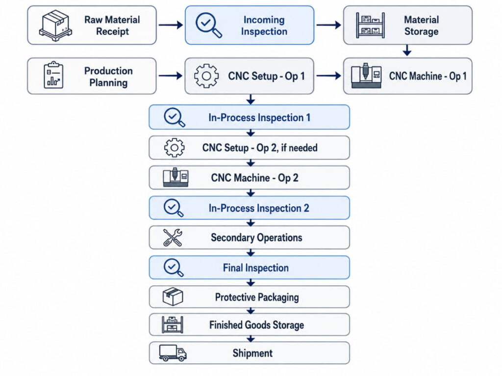
The goal is not to make the diagram overly complicated. The goal is to make it clear enough that a customer can understand how the part is produced and controlled.
What Process Parameters Should Be Identified?
Each operation should include enough detail to connect the process flow with the Control Plan and PFMEA. This usually includes the operation number, operation description, work center or machine identification, key characteristics being produced, and inspection requirements.
For example, instead of writing “Machine part,” a better description would be “CNC Mill: Rough profile and semi-finish pockets.” This gives the customer a clearer understanding of what actually happens at that stage.
Where Should Inspection Points Be Shown?
Inspection points should appear wherever product quality is verified. This may include receiving inspection, first-piece inspection, in-process inspection, last-piece inspection, final inspection, and subcontract receiving inspection.
| Type | When | Purpose | Method |
| First Piece | Start of production | Verify setup | Dimensional check |
| In-Process | During run | Monitor stability | SPC, sampling |
| Last Piece | End of production | Verify completion | Dimensional check |
| 100% | Critical features | Ensure all parts are good | Automated or manual |
| Patrol | Random intervals | System verification | Spot checks |
What Does a CNC Machining Process Flow Look Like?
What Is an Example of a Simple Turned Part Process Flow?
A simple turned part may only require one setup and a small number of operations. In this type of process, the flow is usually easy to show in table form.
| Step | Operation | Equipment | Inspection | Notes |
| 10 | Receive bar stock | Receiving | Visual, count | C36000 cert req’d |
| 20 | Incoming inspection | QC Lab | Chem, dim | Per MIL-I-45208 |
| 30 | Store raw material | Rack A-12 | None | FIFO rotation |
| 40 | Load bar feeder | Lathe L-05 | None | 12-ft bars |
| 50 | CNC Turn, complete | Lathe L-05 | In-process | Auto-inspection |
| 60 | First piece inspect | QC Station | Full layout | Setup approval |
| 70 | Run production | Lathe L-05 | SPC | Hourly samples |
| 80 | 100% deburr | Tumbler T-01 | Visual | 30 min cycle |
| 90 | Final inspection | CMM Room | Full dims | CMM program Q-156 |
| 100 | Package/ship | Shipping | Count, label | Bubble wrap |
What Is an Example of a Multi-Operation Milled Part Process Flow?
A more complex milled part may require multiple setups and inspections between machining operations. This is common when a part needs 4-axis machining or when different sides of the part must be machined separately.
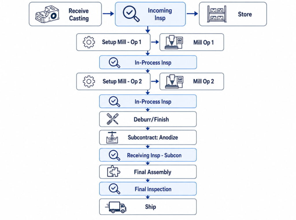
This type of process flow is useful because it shows not only the machining sequence, but also where inspections and subcontract processes take place.
How Should Complex Assemblies Be Shown?
For complex assemblies, it is usually better to create a master process flow. This master flow can reference separate component manufacturing flows, then show how the components move into subassembly, final assembly, and system-level testing.
This approach keeps the main process flow readable while still showing enough detail for customer review.
What Process Flow Diagram Format Should You Use?
When Should You Use a Text-Based Table?
A text-based table works well for simple parts, especially when the process has a limited number of steps. It is easy to prepare, easy to update, and useful when the customer accepts a simple format.
| Op # | Description | Work Center | Characteristics | Inspection |
| 010 | Receive Material | Receiving | N/A | Certificate |
| 020 | Incoming Insp | QC | Chemistry | Per spec |
| 030 | Store | Raw Stk | N/A | None |
| 040 | Turn Op 1 | CNC-01 | OD, lengths | SPC |
| 050 | Turn Op 2 | CNC-01 | Groove, threads | SPC |
| 060 | Deburr | Bench | Burr-free | 100% visual |
| 070 | Final Insp | QC | All dims | CMM |
| 080 | Ship | Shipping | Count | Verify PO |
When Should You Use a Flowchart Diagram?
A flowchart is the standard format for many PPAP submissions because it visually shows how the process moves from one step to another. It can be created using Microsoft Visio, Lucidchart, Draw.io, PowerPoint, Word shapes, or QMS software.
For best results, the flow should move left-to-right or top-to-bottom. Operation numbers should be included, decision branches should be visible, and inspection points should be easy to identify.
When Should You Use a Swimlane Diagram?
A swimlane diagram is useful when the process involves multiple departments or handoffs. For example, a part may move from receiving to production, then to quality control, back to production, and finally to shipping.
Example:
Department:
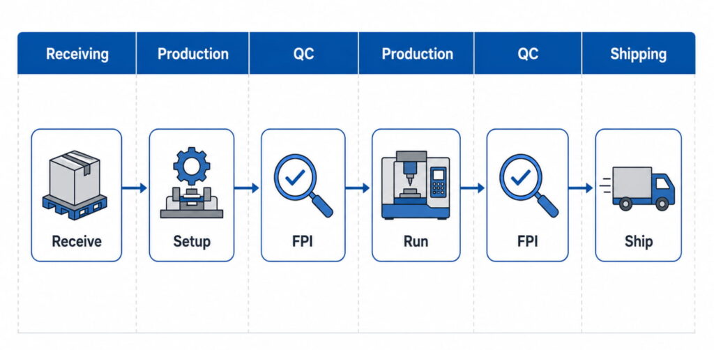
This format is especially useful for identifying responsibilities and preventing confusion between departments.
How Does the Process Flow Link to Other PPAP Documents?
Linking to Control Plan
Every operation in the process flow should have a matching entry in the Control Plan. For example, “Op 50: CNC Turn” in the process flow may correspond to Control Plan Lines 3–5, while “Op 60: In-Process Inspection” may correspond to Control Plan Line 6.
The operation numbers should match across documents. If the process flow and Control Plan use different numbering systems, customers may reject the PPAP submission because the documents do not appear aligned.
Supporting PFMEA?
The process flow provides the structure for the PFMEA. Each process step can become a PFMEA item because each step has potential failure modes. For example, a CNC turning operation may have risks related to incorrect dimensions, tool wear, poor surface finish, or wrong setup.
By using the process flow as the foundation, the PFMEA becomes easier to organize and more closely connected to the actual manufacturing process.
Connecting to Work Instructions?
The process flow shows the sequence of operations, while work instructions explain how each operation should be performed. For example, the process flow may show “CNC Mill Op 1,” while the work instruction explains the setup, tools, program, inspection method, and operator steps.
Referencing work instruction numbers on the process flow helps connect customer-facing documentation with shop floor execution.
What Common Mistakes Should You Avoid?
Missing Inspection Points
A process flow that only shows machining steps is incomplete. Customers want to see how quality is verified throughout the process. This means the diagram should include receiving inspection, in-process inspection, final inspection, and subcontract receiving inspection where applicable.
Vague Operation Descriptions
Descriptions such as “machine part” or “inspect part” are too general. They do not explain what is being produced, controlled, or verified. Clearer descriptions such as “CNC Mill: Rough profile, semi-finish pockets” or “CMM Inspection: Dimensions per Control Plan” make the process easier to understand.
Ignoring Rework Loops
A process flow should show what happens when non-conforming parts are found. If rework is possible, the flow should show how the part returns to the correct operation. If the part must be scrapped or held for disposition, that path should also be clear.
This helps customers see that the supplier has a controlled method for handling quality issues.
Inaccurate Scope
The process flow should include all operations from receipt to shipment, but it should also clearly identify which operations are subcontracted. For example, if anodizing is performed by an outside supplier, the flow should show the part leaving for subcontract processing, returning, and going through receiving inspection.
Diagram Not Matching the Actual Shop Floor Process
One of the biggest mistakes is creating a process flow only for PPAP paperwork. If the diagram does not match what actually happens on the shop floor, it can create audit findings and customer concerns.
The best method is to create the process flow by walking the actual process and confirming each step with production and quality personnel.
What Software Tools Can Be Used for Process Flow Diagrams?
Commercial QMS Software
| Software | Features | Cost |
| EtQ | Integrated QMS, PPAP module | $$$$ |
| IQS | Full APQP/PPAP support | $$$ |
| Intellect | Configurable workflows | $$$ |
| MasterControl | Document control + PPAP | $$$$ |
Diagramming Tools
| Tool | Best For | Cost |
| Microsoft Visio | Professional diagrams | $$ |
| Lucidchart | Collaboration, sharing | $-$$ |
| Draw.io | Free, capable | Free |
| SmartDraw | Templates, automation | $$ |
Can CAD/CAM Systems Help?
Some CAM systems can generate process documentation from programmed operations. Examples include Mastercam, GibbsCAM, Esprit, and FeatureCAM. These tools may be helpful for advanced manufacturers that want to connect CNC programming more closely with process documentation.
Southeast Asia Manufacturing Considerations
In Southeast Asia, CNC machining suppliers often manage customer documentation, shop floor communication, subcontract operations, and regional compliance requirements at the same time. A strong process flow diagram should reflect these realities clearly, especially when serving automotive, aerospace, medical, or industrial customers.
Multilingual Documentation Practices
In Southeast Asia, it is common for customer-facing documentation to be prepared in English while shop floor instructions are written in the local language. This can work well as long as the process flow and work instructions remain aligned.
Visual symbols, photos, and picture-based work instructions can also reduce confusion and make the process easier for operators to follow.
Subcontract Process Control
Subcontracting is common in CNC manufacturing, especially for heat treatment, plating, anodizing, grinding, and other specialized processes. These operations should not be hidden or treated as separate from the process flow.
The diagram should show the subcontract operation in sequence, include transportation steps, and include receiving inspection after the parts return. This proves that the supplier controls the quality of outsourced processes, not just in-house machining.
Thailand Automotive Supplier Requirements
For Thailand automotive manufacturing, suppliers often follow AIAG PPAP 4th Edition. IATF 16949 adoption is also increasing, while Thai Industrial Standards are becoming more aligned with international standards.
To support customer clarity, suppliers should use AIAG standard symbols, include metric and imperial units if the customer requires them, and maintain proper document control.
Who Creates the Process Flow Diagram?
The process flow diagram is usually created through collaboration. The Manufacturing Engineer defines the operations, sequence, and equipment. The Quality Engineer defines inspection points and Control Plan links. Production confirms that the flow matches the actual shop floor process, while the Quality Manager approves the final document.
Although several departments contribute, the Process Owner is usually Manufacturing Engineering.
Process Flow Diagram Detail and Maintenance
A process flow diagram should be detailed enough to show the complete process sequence, identify all inspection points, support the PFMEA, link to the Control Plan, and help the customer understand how the part is manufactured.
However, it should not become a full work instruction. The process flow explains what happens and in what order. The work instruction explains exactly how each task is performed.
Part-Specific vs Generic Process Flows
In most cases, each part number should have its own process flow, especially if the manufacturing route, inspection requirements, or customer requirements are different.
However, part families with identical processes may sometimes share a generic process flow. If this approach is used, any differences between parts must be clearly documented. For high-risk or critical parts, customers may still require part-specific process flows.
Updating Process Flows
Process flows should be updated whenever the manufacturing process changes. This includes new equipment, a different operation sequence, design changes, corrective actions, new inspection requirements, or customer-requested changes.
Even when there are no major changes, process flows should be reviewed regularly as part of the quality management system. Annual review is a common minimum practice.
PPAP Level 3 vs Level 5 Process Flow Requirements
The content of the Process Flow Diagram does not change based on PPAP submission level. The difference is how the document is submitted or reviewed.
For Level 3, the process flow is submitted with the rest of the PPAP package. For Level 5, the process flow is kept at the supplier’s facility and made available for customer review. The document itself should contain the same process information.
Why Would a Customer Reject a Process Flow Diagram?
A customer may reject a PPAP submission if the process flow does not match the Control Plan, PFMEA, or actual production process. Common problems include inconsistent operation numbers, missing inspections, different revision levels, or Control Plan steps that do not appear in the process flow.
The best way to prevent this is to use a cross-reference matrix and update all related PPAP documents together whenever the process changes.
Showing Subcontract Operations Clearly
Subcontract operations should be shown as part of the normal production sequence. They should be clearly labelled, for example, “Subcon: Heat Treatment” or “OUTSIDE: Plating.” The process flow should also show the movement to and from the subcontractor, followed by receiving inspection after the parts return.
Example:
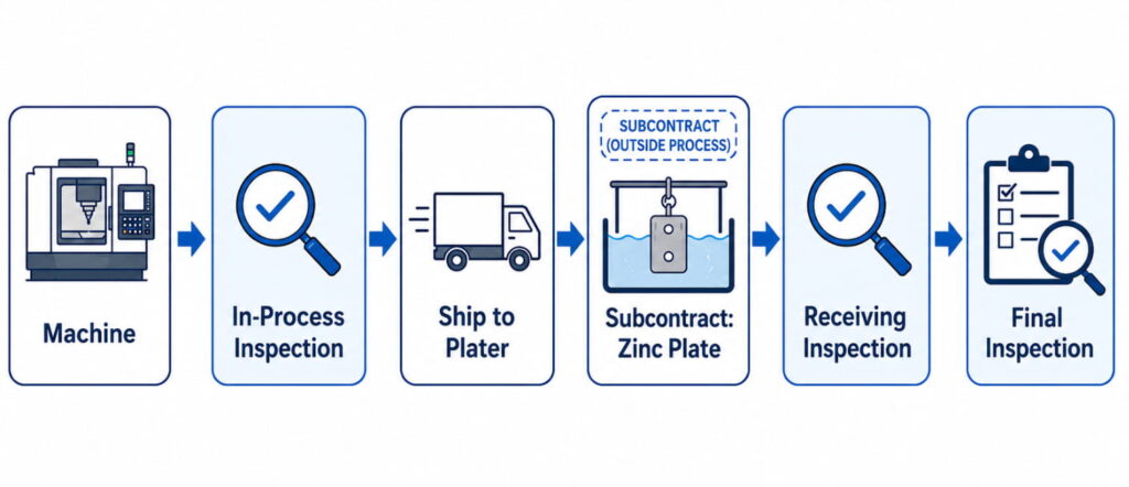
The receiving inspection after subcontracting is important because it confirms that the returned parts meet requirements before the process continues.
Process Flow Diagrams Beyond Automotive Manufacturing
Process flow diagrams are useful even when PPAP is not formally required. Aerospace manufacturers may use similar documentation through FAIR, medical manufacturers need strong process documentation under ISO 13485, and general manufacturers benefit from clearer process control and training.
Even without a customer requirement, a clear process flow can improve internal communication, reduce mistakes, support training, and make audits easier.
Handling Optional Operations in the Process Flow
Optional operations should be shown clearly so that operators, inspectors, and customers understand when they apply. This can be done using a decision diamond, such as “Rework Required?” or by noting “As Required” beside the operation.
For more complex situations, alternate process flows or footnotes may be used. The key is to avoid confusion. Anyone reading the diagram should understand when the optional step is needed and how it connects to the rest of the process.
Conclusion
A Process Flow Diagram is more than a required PPAP document. It is a practical tool that shows how a CNC machining supplier controls the full production journey from raw material receipt to final shipment. When the process flow is accurate, detailed, and aligned with the Control Plan and PFMEA, it gives customers confidence that the supplier understands both the part and the manufacturing process.
For CNC machining companies, a well-prepared process flow diagram can reduce PPAP rejection risk, improve audit readiness, strengthen internal communication, and make production responsibilities clearer. It also helps identify weak points in the process before they become quality issues.In competitive manufacturing markets, strong documentation can be a trust signal. Suppliers that can clearly explain their process, inspection strategy, subcontract controls, and document links are more likely to appear reliable, professional, and ready for demanding automotive, aerospace, medical, and industrial customers.
At Align Manufacturing, we understand that strong process documentation is just as important as the machining or casting process itself. As a Western-owned and operated sourcing and engineering company with operations across Thailand, Vietnam, and India, we help customers move from engineering drawings to reliable finished parts through processes such as investment casting, CNC machining, forging, stamping, and fabrication. Our experience with investment casting steel materials, precision machining, quality control, testing, and shipping allows us to support customers who need both technical manufacturing capability and clear documentation for demanding industrial projects.