
A Technical Deep-Dive into Brass-Specific PFMEA for CNC Operations
In precision manufacturing, the difference between a component that performs flawlessly and one that fails under load often comes down to what was anticipated before machining began. Process Failure Mode and Effects Analysis, or PFMEA, helps manufacturers identify risks before they become costly failures. For brass, a material with unique machining behaviour, generic FMEA templates are often not enough.
For manufacturers working with architectural brass components, material-specific risks such as galling, burr formation, work hardening, and dimensional drift can affect quality, delivery timelines, and customer satisfaction. This guide explains how to apply brass-specific PFMEA in CNC operations for both production facilities and specialized job shops.
What Are the Fundamentals of PFMEA?
The AIAG/VDA 7-Step Approach Explains the Methodology
The AIAG/VDA FMEA Handbook is the current industry standard for process failure analysis. It replaces the older approach with a more structured seven-step method that helps teams identify, evaluate, and reduce risks before they become actual defects.
The Seven PFMEA Steps Guide Risk Identification and Control
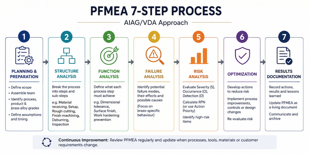
The seven steps of PFMEA are:
- Planning and Preparation: Define the scope, team, timing, and brass alloy grades involved, such as C36000, C46400, and C93200.
- Structure Analysis: Break the process into steps such as material receiving, setup, rough cutting, finish machining, deburring, and inspection.
- Function Analysis: Define what each process step must achieve, such as Ra 0.8 to 1.6 μm surface finish, ±0.05mm tolerance, or prevention of work hardening.
- Failure Analysis: Identify possible failure modes, effects, and causes. This is where brass-specific knowledge is important.
- Risk Analysis: Evaluate Severity, Occurrence, and Detection to calculate RPN, even though the newer AIAG/VDA method also uses Action Priority.
- Optimization: Develop actions to reduce risk through process changes, controls, or design improvements.
- Results Documentation: Record lessons learned and update the PFMEA as a living document.
Standard PFMEA Templates May Not Work Well for Brass
Generic PFMEA templates usually cover common issues such as dimensional variation, surface defects, and tool wear. However, brass, a copper-zinc alloy, has unique properties that require closer attention.
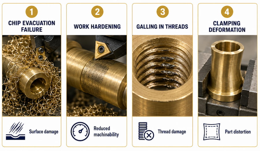
Brass-specific concerns include:
- Galling tendency: Brass’s softness and low melting point create adhesion risks with cutting tools.
- Burr formation: Its ductility can cause burrs that are difficult to remove cleanly.
- Work hardening: Cold working can increase hardness by 20% to 30%, affecting later operations.
- Thermal conductivity: Rapid heat dissipation affects cutting temperatures, tool life, and dimensional stability.
How Do Brass Material Properties Affect Failure Modes?
Different Brass Alloys Create Different CNC Risks
Not all brass alloys behave the same. Composition affects machinability, failure probability, and PFMEA severity ratings.
| Alloy | Composition | Machinability Rating | Key Characteristics | Primary Failure Risks |
| C36000 Free-Cutting Brass | 61.5% Cu, 35.5% Zn, 3% Pb | 100% baseline | Excellent machinability, lead content for chip breaking | Lead distribution, surface lead smearing |
| C46400 Naval Brass | 60% Cu, 39.25% Zn, 0.75% Sn | 30% | High corrosion resistance, added tin | Work hardening, galling |
| C93200 Bearing Bronze | 83% Cu, 7% Sn, 7% Pb, 3% Zn | 50% | High lead content, bearing applications | Porosity, lead segregation |
| C38500 Architectural Bronze | 57% Cu, 40% Zn, 3% Pb | 90% | Good for extrusions and trim | Extrusion seam defects, anisotropic properties |
Material Properties Should Be Linked to Specific Failure Modes
When creating a brass PFMEA, material properties should be connected directly to likely failure modes.
Thermal Conductivity, 109 to 125 W/m·K
- Failure Mode: Cutting edge temperature fluctuation.
- Effect: Thermal cracking of inserts and dimensional instability.
- Occurrence Rating: 6, moderate to high for high-speed operations.
Ductility, 40% to 55% elongation
- Failure Mode: Excessive deformation during cutting.
- Effect: Burr formation, poor finish, and dimensional creep.
- Occurrence Rating: 7, high for finishing operations.
Low Melting Point, 900°C to 940°C
- Failure Mode: Built-up edge formation.
- Effect: Surface tearing, increased cutting forces, and tool wear.
- Occurrence Rating: 5, depending on cutting speed.
Tendency to Work Harden
- Failure Mode: Surface hardness increase during machining.
- Effect: Lower machinability, higher tool wear, and possible cracking.
- Occurrence Rating: 6, moderate to high for interrupted cuts.
How Should PFMEA Be Applied Across CNC Operation Phases?
Setup and Qualification Establish the Foundation for Quality
The setup phase controls the starting accuracy of the process. In brass machining, thermal expansion and workpiece stability are especially important.
Key process elements include:
- Workpiece fixturing and clamping force
- Tool presetting and offset verification
- Machine warm-up and thermal stabilization
- First-piece qualification
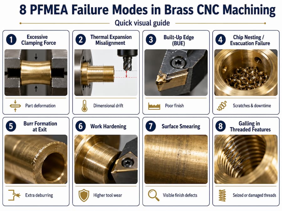
Failure Mode 1: Excessive Clamping Force
- Effect: Workpiece deformation and dimensional non-conformance.
- Severity: 8, due to customer dissatisfaction and assembly issues.
- Cause: Brass has lower yield strength of 124 to 310 MPa compared to steel.
- Current Controls: Torque-limited clamping fixtures and soft jaws.
- RPN: 8 × 6 × 4 = 192, High Priority.
- Recommendation: Use fixture pressure monitoring and specify maximum clamping force in setup sheets.
Failure Mode 2: Thermal Expansion Misalignment
- Effect: Z-axis drift and incorrect depth of cut.
- Severity: 7, due to dimensional variation.
- Cause: Brass thermal expansion coefficient of 20.5 × 10⁻⁶/°C affects positioning.
- Current Controls: Machine warm-up and ambient temperature monitoring.
- RPN: 7 × 5 × 5 = 175, High Priority.
Rough Cutting Requires Heat and Chip Control
Rough machining removes bulk material and establishes basic geometry. For brass, heat generation and chip evacuation are major concerns.
Failure Mode 3: Built-Up Edge Formation
- Effect: Poor surface finish, increased cutting forces, and dimensional variation.
- Severity: 7.
- Cause: Brass adhesion to the tool due to low melting point and high ductility.
- Occurrence: 6, common at moderate cutting speeds.
- Detection: 4, through visual inspection and surface finish measurement.
- RPN: 168.
- Mitigation: Use polished tool coatings such as TiAlN or DLC, cutting speeds of 300 to 600 SFM, and high-pressure coolant.
Failure Mode 4: Chip Nesting and Evacuation Failure
- Effect: Surface scratching, tool damage, and machine downtime.
- Severity: 6.
- Cause: Long, stringy chips from high-ductility brass alloys.
- Occurrence: 5.
- Detection: 3, through machine alarms and visual monitoring.
- RPN: 90.
- Mitigation: Use chip breakers, through-spindle coolant, and programmed chip breaks.
Finish Machining Determines Final Part Quality
Finish operations determine the final dimensions, surface finish, and visible quality of the part.
Failure Mode 5: Burr Formation at Exit
- Effect: Extra deburring, surface damage, and longer cycle time.
- Severity: 6.
- Cause: Brass ductility causes material tearing instead of clean shearing.
- Occurrence: 8, very high for through-features.
- Detection: 4, through visual inspection and touch probe verification.
- RPN: 192.
- Mitigation: Use exit chamfers, sharp cutting edges below 0.01mm hone radius, reduced feed at exit, and back chamfer tools.
Failure Mode 6: Work Hardening During Finishing
- Effect: Higher tool wear in later operations and surface hardness variation.
- Severity: 5.
- Cause: Cold working from previous operations or aggressive cutting parameters.
- Occurrence: 6.
- Detection: 5, through microhardness testing and surface analysis.
- RPN: 150.
- Mitigation: Use intermediate annealing for complex parts, optimized tool paths, and sharp cutting tools.
Deburring and Finishing Protect the Final Appearance
Post-machining operations are especially important for architectural brass components where appearance matters.
Failure Mode 7: Surface Smearing During Deburring
- Effect: Visible defects, uneven patina absorption, and rejected parts.
- Severity: 8, due to aesthetic failure.
- Cause: Brass softness allows abrasive media to embed or smear.
- Occurrence: 6.
- Detection: 3, through visual inspection under magnification.
- RPN: 144.
- Mitigation: Use ceramic media, controlled processing time, and dedicated brass-only finishing equipment.
Failure Mode 8: Galling in Threaded Features
- Effect: Seized fasteners, stripped threads, and field failures.
- Severity: 9, due to potential complete part replacement.
- Cause: Adhesion between brass threads under load, especially with similar brass fasteners.
- Occurrence: 5.
- Detection: 6, through torque testing and thread gauge inspection.
- RPN: 270, Critical Priority.
- Mitigation: Specify anti-seize compound, optimize thread tolerance, and recommend dissimilar fastener materials.
What Failure Modes Should Be Included in a Brass CNC PFMEA?
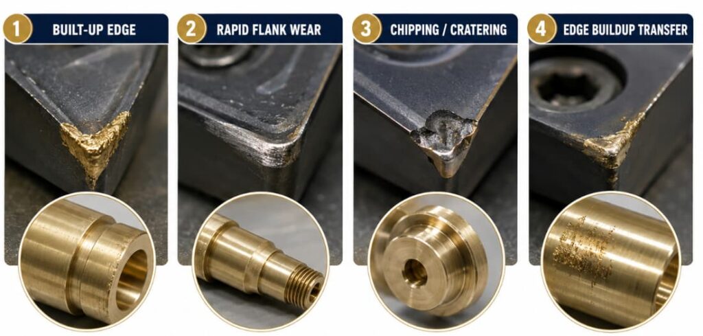
Cutting Tool-Related Failures Can Affect Accuracy and Surface Finish
| Failure Mode | Potential Effect | S | Cause | O | Control | D | RPN | Recommended Action |
| Built-up edge | Poor finish, dimensional drift | 7 | Low speed, uncoated tools | 6 | Tool life monitoring | 4 | 168 | Set minimum SFM and use polished tool coatings |
| Rapid flank wear | Loss of accuracy | 8 | Abrasive constituents, heat | 5 | Scheduled tool changes | 5 | 200 | Optimize parameters and tool wear compensation |
| Chipping/cratering | Sudden tool failure | 9 | Intermittent cutting, vibration | 4 | Tool monitoring | 3 | 108 | Smooth entry/exit and reduce radial engagement |
| Edge buildup transfer | Surface contamination | 6 | BUE break-off | 5 | In-process inspection | 4 | 120 | Improve coolant and chip evacuation |
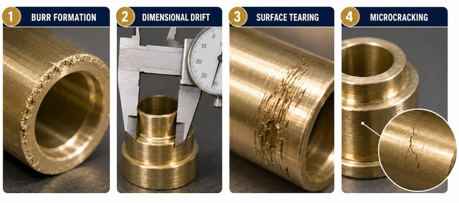
Workpiece-Related Failures Can Cause Burrs, Drift, and Cracking
| Failure Mode | Potential Effect | S | Cause | O | Control | D | RPN | Recommended Action |
| Burr formation | Extra processing, surface damage | 6 | Ductile material behaviour | 8 | Visual inspection | 4 | 192 | Optimize exit strategy and use back chamfering |
| Dimensional drift | Assembly interference | 8 | Thermal expansion, work hardening | 5 | In-process probing | 4 | 160 | Use thermal compensation and intermediate checks |
| Surface tearing | Aesthetic rejection | 8 | BUE, dull tools | 5 | Surface finish check | 3 | 120 | Improve tool condition and parameters |
| Microcracking | Weakness, corrosion initiation | 9 | Excessive work hardening | 4 | Dye penetrant inspection | 6 | 216 | Use stress relief and review parameters |
Process-Related Failures Can Lead to Rework or Rejection
| Failure Mode | Potential Effect | S | Cause | O | Control | D | RPN | Recommended Action |
| Chip evacuation failure | Surface damage, tool breakage | 7 | Stringy chips, poor coolant | 6 | Machine alarms | 3 | 126 | Use high-pressure coolant and maintain conveyors |
| Work hardening | Reduced machinability | 6 | Excessive cold working | 6 | Hardness testing | 5 | 180 | Optimize depth of cut and consider annealing |
| Galling in threads | Seizure, fastener failure | 9 | Material adhesion | 5 | Torque testing | 6 | 270 | Use anti-seize and review thread design |
| Clamping deformation | Dimensional non-conformance | 8 | Excessive force | 6 | Setup verification | 4 | 192 | Use torque-limited fixtures and soft jaws |
How Does a Brass Architectural Component PFMEA Work in Practice?
A Custom Brass Door Hardware Component Shows Common PFMEA Risks
Part Description: Solid brass lever handle made from C36000, requiring precision machining of mounting features, threaded insert bores, and mirror-finish visible surfaces.
Manufacturing Process Flow:
- Bar stock receiving and inspection
- CNC turning, rough and finish
- CNC milling, mounting features
- Thread milling, M8 mounting threads
- Deburring and surface finishing
- Protective lacquer application
- Final inspection and packaging
The PFMEA Excerpt Highlights Finish Turning Issues
Process Step: CNC Turning, Finish Profile
Function: Generate final handle profile to ±0.1mm tolerance with Ra 0.4 μm surface finish on visible surfaces.
| Failure Mode | Potential Effect | S | Cause | O | Prevention | Detection | D | RPN | Action Recommended |
| Visible burr at shoulder | Customer rejection | 8 | Ductile tearing at exit | 7 | Lead-out, sharp tools | 100% visual inspection | 3 | 168 | Add back-turning and reduce feed 50% at exit |
| Diameter variation | Assembly interference | 8 | Thermal expansion, tool wear | 5 | Tool tracking, constant SFM | In-process probing | 4 | 160 | Add mid-batch probe check and wear compensation |
| Surface finish non-conformance | Aesthetic rejection | 7 | BUE, improper feed/speed | 6 | Parameter cards, coated inserts | Roughness check | 4 | 168 | Use TiAlN inserts and optimize feed |
| Work hardening in bore | Thread milling difficulty | 6 | Aggressive roughing | 6 | Roughing limits | Hardness spot check | 5 | 180 | Reduce roughing depth and add stress relief |
Recommended Actions Can Reduce RPN and Improve Yield
After implementing the recommended actions, RPN values were reduced:
- Visible burr: 168 to 72, a 57% reduction
- Dimensional variation: 160 to 96, a 40% reduction
- Surface finish: 168 to 84, a 50% reduction
- Work hardening: 180 to 90, a 50% reduction
First-pass yield improved from 87% to 96%, and surface-quality complaints dropped to zero over six months.
How Can SPC Be Integrated with PFMEA and Control Plans?
PFMEA Should Be Linked to Statistical Process Control
A PFMEA without Statistical Process Control, or SPC, is only a theoretical exercise. The value comes when risk prevention becomes real-time monitoring.
Control Plans Should Be Developed from High-Risk Failure Modes
For each high-RPN failure mode, the control plan should define the control method, measurement technique, sample frequency, control limits, and reaction plan.
SPC Chart Selection Should Match the Failure Mode
| Failure Mode | SPC Chart Type | Rationale | Key Variables |
| Dimensional drift | X-bar and R Chart | Monitors average and variation | Diameter, length |
| Surface finish | Individual-X and Moving Range | Suitable for low-volume checks | Ra values |
| Tool wear trend | CUSUM or EWMA | Detects small changes early | Tool compensation values |
| Burr occurrence | p-chart or np-chart | Tracks pass/fail results | Burr presence |
| Work hardening | Individual-X | Suitable for batch checks | Microhardness readings |
Digital Integration Can Connect PFMEA to MES Systems
Modern Manufacturing Execution Systems, or MES, can connect PFMEA data to production workflows. This supports automated inspection triggers, real-time alerts, closed-loop feedback, and traceability across material lots, process parameters, and inspection results.
How Should Job Shops and Production Facilities Adapt PFMEA?
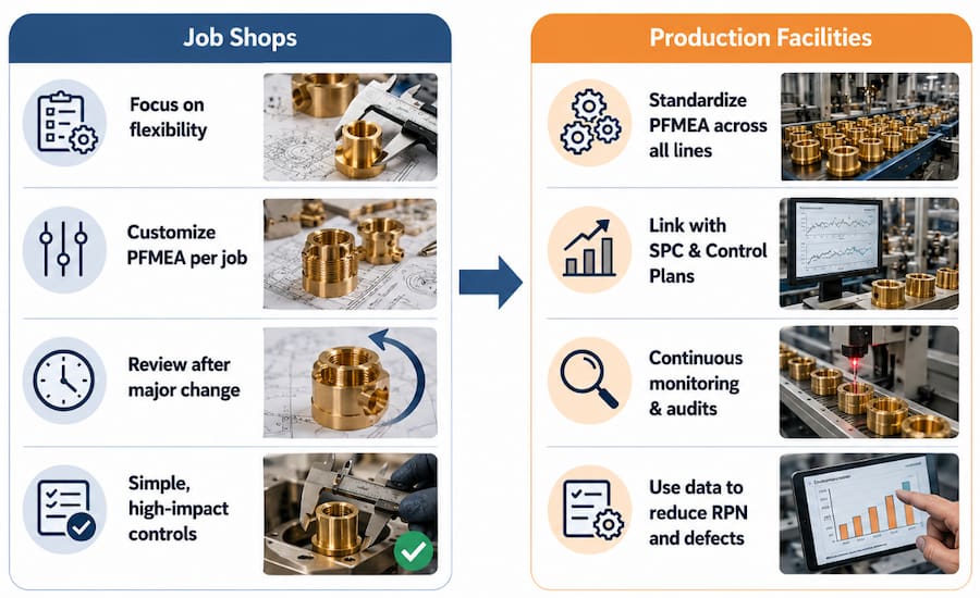
Job Shops Face Small-Batch PFMEA Challenges
Job shops often face lower production volumes, higher part variety, limited quality engineering resources, and changing customer requirements.
Generic Process PFMEA Templates Help Reduce Repeated Work
Job shops can create master PFMEAs for process families instead of starting from zero each time. Examples include:
- Brass Turning Operations, C36000
- Brass Milling Operations, All Alloys
- Brass Thread Generation
These templates can then be adapted for each new part.
Risk-Based Sampling Helps Prioritize Important Features
Not all features need the same level of scrutiny.
Class A, Critical: Safety-related features, customer-specified critical features, and tolerances below ±0.05mm.
Approach: Full PFMEA with all recommended actions.
Class B, Major: Functional but not safety-critical features, with tolerances of ±0.05mm to ±0.2mm.
Approach: Standard PFMEA with actions for RPN values above 150.
Class C, Minor: Aesthetic or non-critical features, with tolerances above ±0.2mm.
Approach: Abbreviated PFMEA focused on the highest-risk issues.
Pre-Validated Process Windows Support Faster Decision-Making
| Operation | Cutting Speed, SFM | Feed Rate, mm/rev | Depth of Cut, mm | Validated For |
| Rough Turning | 400 to 600 | 0.15 to 0.25 | 2.0 to 5.0 | C36000, C38500 |
| Finish Turning | 500 to 800 | 0.05 to 0.15 | 0.25 to 1.0 | C36000, C38500 |
| Rough Milling | 300 to 500 | 0.10 to 0.20 | 3.0 to 6.0 | All brass grades |
| Finish Milling | 400 to 700 | 0.05 to 0.10 | 0.2 to 0.5 | All brass grades |
When parameters stay within proven windows, some failure modes can receive lower occurrence ratings.
ASEAN Manufacturers Should Consider Supplier, Climate, and Workforce Factors
For ASEAN manufacturing, PFMEA should also consider supplier quality variation, mill test reports, incoming material testing, high humidity, temperature variation, power quality, workforce training, language barriers, and escalation procedures.
How Should RPN and Action Priority Be Used for Brass CNC Operations?
RPN Helps Evaluate and Rank Process Risk
Although the AIAG/VDA method now uses Action Priority, RPN is still widely used.
RPN Formula: RPN = Severity × Occurrence × Detection
| Rating | Severity | Occurrence | Detection |
| 1 | No effect | ≤ 1 in 1,500,000 | Almost certain |
| 2 to 3 | Minor annoyance | 1 in 150,000 to 1 in 15,000 | High probability |
| 4 to 6 | Moderate effect | 1 in 2,000 to 1 in 100 | Moderate probability |
| 7 to 8 | High impact | 1 in 50 to 1 in 10 | Low probability |
| 9 to 10 | Safety or critical | ≥ 1 in 5 | Very low or none |
RPN Thresholds Help Prioritize Corrective Actions
| RPN Range | Priority | Action Required |
| 1 to 80 | Low | Monitor |
| 81 to 150 | Moderate | Action recommended |
| 151 to 250 | High | Action required |
| 251 to 400 | Critical | Immediate action and escalation |
| 401 to 1000 | Emergency | Stop production until mitigated |
Brass Requires Special Attention for Severity and Detection
Safety-related failures with Severity 9 to 10 should always be addressed. Galling in structural threads should be treated as critical, and stress corrosion cracking should receive elevated severity for outdoor applications.
Detection can also be difficult. Microcracks may require dye penetrant inspection, subsurface work hardening may require destructive testing, and surface smearing can hide defects.
Why Is Brass-Specific PFMEA Important for CNC Operations?
PFMEA is not just a checklist. It is a living method for turning reactive quality management into proactive risk control. For brass CNC operations, a material-specific PFMEA can help reduce rework, improve first-pass yield, and prevent quality escapes.
The framework in this guide gives teams a practical starting point. However, the real value comes from applying it to specific machines, parts, processes, and customer requirements. PFMEAs should be updated as processes change, and each failure should be treated as a chance to improve future risk assessment.
For job shops, a strong PFMEA supports better quoting, fewer rejected parts, and higher customer confidence. For production facilities, linking PFMEA with SPC creates a closed-loop quality system where data supports continuous improvement.
Reference Tables
Brass Grade Selection Helps Match Applications to PFMEA Focus Areas
| Application | Recommended Grade | Key PFMEA Focus |
| Interior hardware | C36000 | Lead distribution, surface smearing |
| Exterior or marine hardware | C46400 | Work hardening, galling prevention |
| Bearing surfaces | C93200 | Porosity, lead segregation |
| Architectural extrusions | C38500 | Anisotropic properties, seam defects |
Cutting Parameter Tables Support Process Planning
| Operation | SFM Range | Feed, mm/rev | Depth, mm | Coolant |
| Rough Turn | 400 to 600 | 0.15 to 0.25 | 2.0 to 5.0 | Flood soluble |
| Finish Turn | 500 to 800 | 0.05 to 0.15 | 0.25 to 1.0 | High-pressure |
| Rough Mill | 300 to 500 | 0.10 to 0.20 per tooth | 3.0 to 6.0 | Through-spindle |
| Finish Mill | 400 to 700 | 0.05 to 0.10 per tooth | 0.2 to 0.5 | Mist or minimal |
Common Failure Mode Tables Help Teams Diagnose Issues Quickly
| Failure Mode | Most Common Causes | Quick Check |
| Burr formation | Dull tools, fast exit feed, high ductility | Tool condition and exit strategy |
| Galling | Similar materials, no lubrication, high load | Fastener material and anti-seize use |
| Work hardening | Large depths of cut, slow speeds, dull tools | Cutting parameters and tool sharpness |
| Built-up edge | Moderate speeds, uncoated tools, high ductility | Cutting speed and tool coating |
| Dimensional drift | Thermal effects, tool wear, machine warm-up | Thermal compensation and tool life tracking |
Conclusion
Brass-specific PFMEA is essential for CNC operations because brass does not behave the same way as steel, aluminium, or other common engineering materials. Its ductility, low melting point, galling tendency, burr formation risk, and work hardening behaviour can all affect machining quality if they are not properly controlled. By identifying these risks early, manufacturers can reduce rework, improve first-pass yield, protect surface quality, and maintain tighter control over production outcomes.
A strong PFMEA should not be treated as a one-time checklist. It should be updated as tools, machines, materials, suppliers, and customer requirements change. When PFMEA is connected with SPC, control plans, inspection routines, and real-time production feedback, it becomes a practical system for preventing failures before they affect delivery timelines or customer satisfaction.
At Align Manufacturing, we understand that successful brass CNC production depends on more than machining capability alone. From our perspective, reliable sourcing, clear communication, supplier control, quality inspection, and process discipline are just as important as cutting parameters. As companies look for dependable Vietnam precision machining solutions, we help connect projects with trusted manufacturing partners across Vietnam and the wider region, supporting customers from engineering review to production, inspection, and logistics.