
Custom Architectural Brass: Machining, Forming, and Finishing for Design
A Technical Deep-Dive into Brass-Specific PFMEA for CNC Operations
In precision manufacturing, the difference between a component that performs flawlessly and one that fails under load often comes down to what you anticipated before the first chip hit the floor. Process Failure Mode and Effects Analysis (PFMEA) is the systematic methodology that separates reactive manufacturers from proactive ones,and when it comes to brass, a material with unique behavioral characteristics, generic FMEA templates simply won’t suffice.
For manufacturers working with architectural brass components, understanding material-specific failure modes isn’t optional. Galling, burr formation, work hardening, and dimensional drift each represent potential quality catastrophes that can derail production schedules, inflate costs, and damage client relationships. This guide provides a comprehensive framework for implementing brass-specific PFMEA in CNC operations, with practical applications for both high-volume production environments and specialized job shops serving the ASEAN manufacturing ecosystem.
Section 1: PFMEA Fundamentals – The AIAG/VDA 7-Step Approach
Understanding the Methodology
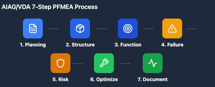
The AIAG/VDA FMEA Handbook represents the current industry standard for process failure analysis, replacing the traditional 4th edition approach with a more structured seven-step methodology. This framework provides the foundation for identifying, evaluating, and mitigating risks before they manifest as actual failures.
The Seven Steps of PFMEA:
- Planning and Preparation: Define the scope, team, and timing of the analysis. For brass CNC operations, this includes identifying specific alloy grades (C36000, C46400, C93200) and their unique processing requirements.
- Structure Analysis: Break down the manufacturing process into individual process steps, work elements, and focus elements. A brass CNC operation might include: material receiving, setup/qualification, rough cutting, finish machining, deburring, and inspection.
- Function Analysis: Document what each process element is supposed to achieve. For brass finish machining, this might include achieving specified surface finish (Ra 0.8-1.6 μm), maintaining dimensional tolerances (±0.05mm), and preventing work hardening.
- Failure Analysis: Identify potential failure modes, their effects, and root causes. This is where brass-specific knowledge becomes critical—standard FMEA templates designed for steel or aluminum often miss material-specific failure mechanisms.
- Risk Analysis: Calculate Risk Priority Numbers (RPN) using Severity (S), Occurrence (O), and Detection (D) ratings. The new AIAG/VDA method replaces RPN with Action Priority (AP) levels, though RPN remains widely used in practice.
- Optimization: Develop and implement mitigation strategies to reduce risk. This includes process changes, additional controls, or design modifications.
- Results Documentation: Capture lessons learned and update the PFMEA as a living document.
Why Standard PFMEA Templates Fall Short for Brass
Generic PFMEA templates typically address common failure modes across all materials: dimensional variation, surface defects, and tool wear. However, brass, which a copper-zinc alloy with distinct mechanical properties, presents unique challenges that demand specialized attention:
- Galling tendency: Brass’s softness and low melting point create adhesion risks with cutting tools
- Burr formation propensity: Ductility leads to burrs that are difficult to remove without surface damage
- Work hardening characteristics: Cold working can increase hardness by 20-30%, affecting subsequent operations
- Thermal conductivity: Rapid heat dissipation affects cutting temperatures and tool life
A PFMEA that doesn’t account for these brass-specific behaviors leaves manufacturers vulnerable to predictable, preventable failures.
Section 2: Brass Material Properties and Failure Mode Correlation
Understanding Brass Alloys in CNC Applications
Not all brass is created equal. The alloy composition directly impacts machinability, failure mode probability, and appropriate PFMEA severity ratings.
Common Architectural Brass Grades:
| Alloy | Composition | Machinability Rating | Key Characteristics | Primary Failure Risks |
| C36000 (Free-Cutting Brass) | 61.5% Cu, 35.5% Zn, 3% Pb | 100% (baseline) | Excellent machinability, lead content for chip breaking | Lead distribution uniformity, surface lead smearing |
| C46400 (Naval Brass) | 60% Cu, 39.25% Zn, 0.75% Sn | 30% | High corrosion resistance, added tin | Work hardening, galling with high-speed cutting |
| C93200 (Bearing Bronze) | 83% Cu, 7% Sn, 7% Pb, 3% Zn | 50% | High lead content, bearing applications | Porosity, lead segregation |
| C38500 (Architectural Bronze) | 57% Cu, 40% Zn, 3% Pb | 90% | Good for extrusions, architectural trim | Extrusion seam defects, anisotropic properties |
Material Property Correlation Table for PFMEA
When developing your PFMEA, correlate material properties with specific failure modes:
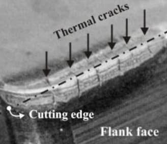
Thermal Conductivity (109-125 W/m·K):
- Failure Mode: Rapid heat dissipation causes cutting edge temperature fluctuations
- Effect: Thermal cracking of carbide inserts, dimensional instability
- Occurrence Rating: 6 (moderate to high for high-speed operations)
Ductility (40-55% elongation):
- Failure Mode: Excessive material deformation during cutting
- Effect: Burr formation, poor surface finish, dimensional creep
- Occurrence Rating: 7 (high for finishing operations)
Low Melting Point (900-940°C):
- Failure Mode: Built-up edge (BUE) formation on cutting tool
- Effect: Surface tearing, increased cutting forces, accelerated tool wear
- Occurrence Rating: 5 (moderate, depends on cutting speed)
Tendency to Work Harden:
- Failure Mode: Surface hardness increase during machining
- Effect: Reduced machinability in subsequent passes, increased tool wear, potential for cracking
- Occurrence Rating: 6 (moderate to high for interrupted cuts)
Section 3: CNC Operation Phases – Phase-Specific PFMEA
Phase 1: Setup and Qualification
The setup phase establishes the foundation for all subsequent operations. In brass machining, thermal expansion and workpiece stability are critical considerations.
Key Process Elements:
- Workpiece fixturing and clamping force
- Tool presetting and offset verification
- Machine warm-up and thermal stabilization
- First-piece qualification
Brass-Specific Failure Modes:
Failure Mode 1: Excessive Clamping Force
- Effect: Workpiece deformation, dimensional non-conformance
- Severity: 8 (customer dissatisfaction, potential assembly issues)
- Cause: Brass’s lower yield strength (124-310 MPa) compared to steel
- Current Controls: Torque-limited clamping fixtures, soft jaw design
- RPN: 8 × 6 × 4 = 192 (High Priority)
- Recommendation: Implement fixture pressure monitoring, specify maximum clamping force in setup sheets
Failure Mode 2: Thermal Expansion Misalignment
- Effect: Z-axis drift, incorrect depth of cut
- Severity: 7 (dimensional variation)
- Cause: Brass thermal expansion coefficient (20.5 × 10⁻⁶/°C) affecting positioning
- Current Controls: Machine warm-up procedures, ambient temperature monitoring
- RPN: 7 × 5 × 5 = 175 (High Priority)
Phase 2: Rough Cutting
Rough machining removes bulk material and establishes basic geometry. For brass, heat generation and chip evacuation are primary concerns.
Key Process Elements:
- Spindle speed selection (SFM optimization)
- Feed rate programming
- Depth of cut determination
- Coolant application strategy
Brass-Specific Failure Modes:
Failure Mode 3: Built-Up Edge Formation
- Effect: Poor surface finish, increased cutting forces, dimensional variation
- Severity: 7
- Cause: Brass adhesion to tool due to low melting point and high ductility
- Occurrence: 6 (common at moderate cutting speeds)
- Detection: 4 (visual inspection, surface finish measurement)
- RPN: 168
- Mitigation: Polished tool coatings (TiAlN, DLC), optimal cutting speeds (300-600 SFM), high-pressure coolant
Failure Mode 4: Chip Nesting and Evacuation Failure
- Effect: Surface scratching, tool damage, machine downtime
- Severity: 6
- Cause: Long, stringy chips typical of high-ductility brass alloys
- Occurrence: 5
- Detection: 3 (machine alarm, visual monitoring)
- RPN: 90
- Mitigation: Chip breakers, high-pressure through-spindle coolant, programmed chip breaks (peck drilling cycles)
Phase 3: Finish Machining
Finish operations determine final part quality and must account for brass’s propensity for surface deformation.
Key Process Elements:
- Finish tool path programming
- Final dimension achievement
- Surface finish generation
- Burr minimization
Brass-Specific Failure Modes:
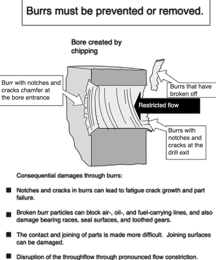
Failure Mode 5: Burr Formation at Exit
- Effect: Additional deburring operations, potential surface damage, increased cycle time
- Severity: 6
- Cause: Brass ductility causes material tearing rather than clean shearing
- Occurrence: 8 (very high for through-features)
- Detection: 4 (visual inspection, touch probe verification)
- RPN: 192
- Mitigation: Exit chamfer programming, sharp cutting edges (hone radius <0.01mm), reduced feed at exit, back chamfer tools
Failure Mode 6: Work Hardening During Finishing
- Effect: Increased tool wear in subsequent operations, surface hardness variation
- Severity: 5
- Cause: Cold working from previous operations or aggressive cutting parameters
- Occurrence: 6
- Detection: 5 (microhardness testing, surface analysis)
- RPN: 150
- Mitigation: Intermediate annealing for complex parts, optimized tool paths minimizing rub, sharp cutting tools
Phase 4: Deburring and Finishing
Post-machining operations are critical for brass architectural components where aesthetics matter.
Key Process Elements:
- Mechanical deburring (tumbling, vibratory finishing)
- Manual deburring operations
- Surface treatment application
- Protective coating or patination
Brass-Specific Failure Modes:
Failure Mode 7: Surface Smearing During Deburring
- Effect: Visible surface defects, uneven patina absorption, rejected parts
- Severity: 8 (aesthetic failure on visible components)
- Cause: Brass softness allows abrasive media to embed or smear
- Occurrence: 6
- Detection: 3 (visual inspection under magnification)
- RPN: 144
- Mitigation: Ceramic media selection, controlled processing time, dedicated brass-only finishing equipment
Failure Mode 8: Galling in Threaded Features
- Effect: Seized fasteners, stripped threads, field failures
- Severity: 9 (potential for complete part replacement)
- Cause: Adhesion between brass threads under load, especially with similar brass fasteners
- Occurrence: 5
- Detection: 6 (torque testing, thread gauge inspection)
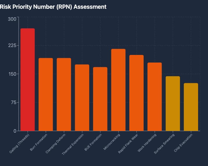
- RPN: 270 (Critical Priority)
- Mitigation: Anti-seize compound specification, thread class tolerance optimization, dissimilar material fastener recommendations
Section 4: Brass CNC Failure Mode Library
Comprehensive Failure Mode Database
This reference library provides pre-evaluated failure modes specific to brass CNC operations, serving as a starting point for your PFMEA development.
Cutting Tool-Related Failures
| Failure Mode | Potential Effect | S | Cause | O | Current Control | D | RPN | Recommended Action |
| Built-up edge formation | Poor surface finish, dimensional drift | 7 | Low cutting speed, uncoated tools | 6 | Tool life monitoring | 4 | 168 | Implement minimum SFM requirements; specify polished tool coatings |
| Rapid flank wear | Loss of dimensional accuracy | 8 | Abrasive brass constituents, high cutting temps | 5 | Scheduled tool changes | 5 | 200 | Optimize cutting parameters; implement tool wear compensation |
| Chipping/cratering | Sudden tool failure, part damage | 9 | Intermittent cutting, vibration | 4 | Tool condition monitoring | 3 | 108 | Program smooth entry/exit; reduce radial engagement |
| Edge buildup transfer | Surface contamination | 6 | BUE break-off during cutting | 5 | In-process inspection | 4 | 120 | Increase coolant concentration; improve chip evacuation |
Workpiece-Related Failures
| Failure Mode | Potential Effect | S | Cause | O | Current Control | D | RPN | Recommended Action |
| Burr formation | Additional processing, surface damage | 6 | Ductile material behavior | 8 | Visual inspection | 4 | 192 | Optimize exit strategy; implement back chamfering |
| Dimensional drift | Assembly interference | 8 | Thermal expansion, work hardening | 5 | In-process probing | 4 | 160 | Thermal compensation algorithms; intermediate measurement |
| Surface tearing | Aesthetic rejection | 8 | Built-up edge, dull tools | 5 | Surface finish check | 3 | 120 | Tool condition protocols; cutting parameter optimization |
| Microcracking | Structural weakness, corrosion initiation | 9 | Excessive work hardening | 4 | Dye penetrant inspection | 6 | 216 | Stress relief annealing; process parameter review |
Process-Related Failures
| Failure Mode | Potential Effect | S | Cause | O | Current Control | D | RPN | Recommended Action |
| Chip evacuation failure | Surface damage, tool breakage | 7 | Stringy chips, inadequate coolant | 6 | Machine alarms | 3 | 126 | High-pressure coolant; chip conveyor maintenance |
| Work hardening | Reduced machinability | 6 | Excessive cold working | 6 | Hardness testing | 5 | 180 | Optimize depth of cut; consider annealing cycles |
| Galling (threaded features) | Seizure, fastener failure | 9 | Material adhesion under load | 5 | Torque testing | 6 | 270 | Anti-seize protocol; thread design review |
| Clamping deformation | Dimensional non-conformance | 8 | Excessive force on soft material | 6 | Setup verification | 4 | 192 | Torque-limited fixtures; soft jaw implementation |
Section 5: Case Study – Brass Architectural Component PFMEA Walkthrough
Scenario: Custom Brass Door Hardware Component
Part Description: Solid brass lever handle (C36000) requiring precision machining of mounting features, threaded insert bores, and aesthetic surfaces requiring mirror finish on visible faces.
Manufacturing Process Flow:
- Bar stock receiving and inspection
- CNC turning (rough and finish)
- CNC milling (mounting features)
- Thread milling (M8 mounting threads)
- Deburring and surface finishing
- Protective lacquer application
- Final inspection and packaging
Detailed PFMEA Excerpt
Process Step: CNC Turning – Finish Profile Function: Generate final handle profile to ±0.1mm tolerance with Ra 0.4 μm surface finish on visible surfaces
| Failure Mode | Potential Effect | S | Potential Cause | O | Current Prevention | Current Detection | D | RPN | Action Recommended | Resp | Target Date |
| Visible surface burr at shoulder | Customer rejection, aesthetic failure | 8 | Ductile material tearing at tool exit | 7 | Programmed lead-out; sharp tools | Visual inspection 100% | 3 | 168 | Implement back-turning operation; reduce feed 50% at exit | Process Eng | 15/06/2026 |
| Dimensional variation in diameter | Assembly interference or looseness | 8 | Thermal expansion during cutting; tool wear | 5 | Tool life tracking; constant SFM | In-process probing | 4 | 160 | Add diameter probe check mid-batch; implement tool wear compensation | QC Mgr | 22/06/2026 |
| Surface finish non-conformance (Ra > 0.4) | Aesthetic rejection, patina variation | 7 | BUE formation; improper feed/speed | 6 | Parameter cards; coated inserts | Surface roughness check | 4 | 168 | Specify TiAlN coated inserts; optimize feed to 0.1mm/rev | Manufacturing Eng | 15/06/2026 |
| Work hardening in bore | Thread milling difficulty, tool wear | 6 | Aggressive roughing parameters | 6 | Roughing parameter limits | Hardness spot check | 5 | 180 | Reduce roughing depth of cut; add stress-relief anneal step | Materials Eng | 29/06/2026 |
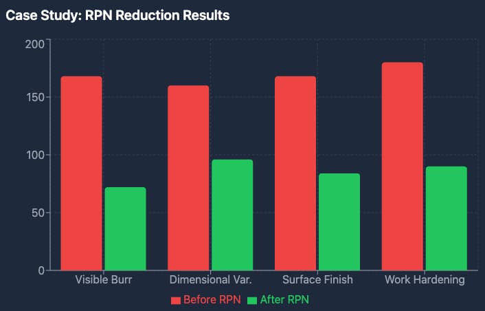
Post-Implementation Results: Following implementation of recommended actions, the RPN values were reduced as follows:
- Visible burr: 168 → 72 (57% reduction)
- Dimensional variation: 160 → 96 (40% reduction)
- Surface finish: 168 → 84 (50% reduction)
- Work hardening: 180 → 90 (50% reduction)
First-pass yield improved from 87% to 96%, and customer complaints related to surface quality dropped to zero over a six-month period.
Section 6: SPC Integration – From PFMEA to Control Plans
Linking PFMEA to Statistical Process Control
A PFMEA without integration to Statistical Process Control (SPC) is a theoretical exercise. The true value emerges when failure mode prevention translates to real-time process monitoring.
Control Plan Development from PFMEA:
For each high-RPN failure mode identified in your PFMEA, develop corresponding control plan elements:
- Control Method: How will you prevent or detect the failure?
- Measurement Technique: What specific measurement tools and methods apply?
- Sample Size/Frequency: How often and how many samples?
- Control Limits: What constitutes acceptable vs. concerning variation?
- Reaction Plan: What happens when controls indicate a problem?
SPC Chart Selection for Brass CNC Operations
| Failure Mode | SPC Chart Type | Rationale | Key Variables |
| Dimensional drift | X-bar and R Chart | Monitor central tendency and variation simultaneously | Critical dimensions (diameter, length) |
| Surface finish | Individual-X and Moving Range | Destructive or expensive measurement, low volume | Ra values from surface profilometer |
| Tool wear trend | CUSUM or EWMA | Detect small, persistent changes before they become problems | Tool length compensation values |
| Burr occurrence | p-chart or np-chart | Attribute data (pass/fail), track proportion defective | Burr presence at critical features |
| Work hardening | Individual-X | Batch processing, moderate frequency | Microhardness readings |
Control Plan Example: Brass Finish Turning
Control Plan Reference: CP-BR-FT-001 Part/Process: Finish turning operation on C36000 brass components PFMEA Reference: PFMEA-BR-003
| Characteristic | Specification | Control Method | Measurement | Sample Size | Frequency | Control Limits | Reaction Plan |
| Diameter | 25.00 ± 0.05mm | X-bar & R Chart | CMM or micrometer | 5 parts | Hourly | UCL: 25.03, LCL: 24.97 | Stop production; adjust offset; quarantine last hour |
| Surface finish | Ra ≤ 0.8 μm | Individual-X | Surface profilometer | 1 part | Every 4 hours | UCL: 0.7 μm | Replace insert; inspect last 10 parts |
| Burr presence | No visible burrs | Attribute check | Visual/magnification | 100% | Continuous | 0 defects | Rework part; adjust tool path |
| Tool wear | < 0.05mm flank wear | Tool presetting | Tool scope | All tools | Per change | Max 0.05mm | Change tool; inspect first part |
Digital Integration: PFMEA to MES Systems
Modern Manufacturing Execution Systems (MES) can integrate PFMEA data directly into production workflows:
- Automated Inspection Triggers: High-RPN failure modes automatically generate inspection work instructions
- Real-time Alerts: SPC violations trigger immediate notifications to production and quality personnel
- Closed-loop Feedback: Inspection results feed back into PFMEA occurrence ratings for continuous improvement
- Traceability: Complete part genealogy linking material lots, process parameters, and inspection results
Section 7: Job Shop vs. Production PFMEA Adaptation
The Small-Batch Challenge
Job shops face unique PFMEA challenges compared to mass production facilities:
- Lower volume: Statistical data may be limited or non-existent for specific part numbers
- Higher variety: Each new part requires PFMEA development from scratch or adaptation
- Resource constraints: Limited quality engineering bandwidth for comprehensive analysis
- Customer variability: Different clients may have conflicting quality requirements
Adaptive PFMEA Strategies for Job Shops
Strategy 1: Generic Process PFMEA Templates
Develop master PFMEAs for process families rather than individual parts:
- Template: Brass Turning Operations (C36000)
- Template: Brass Milling Operations (All Alloys)
- Template: Brass Thread Generation
When a new part arrives, adapt the template rather than starting from zero.
Strategy 2: Risk-Based Sampling
Not all features require the same level of scrutiny:
- Class A (Critical): Safety-related, customer-specified critical, tight tolerances (< ±0.05mm)
- Approach: Full PFMEA with all recommended actions implemented
- Class B (Major): Functional but not safety-critical, moderate tolerances (±0.05-0.2mm)
- Approach: Standard PFMEA with actions for RPN > 150
- Class C (Minor): Aesthetic or non-critical, loose tolerances (> ±0.2mm)
- Approach: Abbreviated PFMEA focusing on highest-risk failure modes only
Strategy 3: Pre-validated Process Windows
Establish proven parameter ranges for brass machining:
| Operation | Cutting Speed (SFM) | Feed Rate (mm/rev) | Depth of Cut (mm) | Validated For |
| Rough Turning | 400-600 | 0.15-0.25 | 2.0-5.0 | C36000, C38500 |
| Finish Turning | 500-800 | 0.05-0.15 | 0.25-1.0 | C36000, C38500 |
| Rough Milling | 300-500 | 0.10-0.20 | 3.0-6.0 | All brass grades |
| Finish Milling | 400-700 | 0.05-0.10 | 0.2-0.5 | All brass grades |
When parameters stay within validated windows, certain failure modes can be assigned lower occurrence ratings.
ASEAN Manufacturing Context
For manufacturers operating in or sourcing from ASEAN markets, additional PFMEA considerations apply:
Supplier Quality Variability:
- Material certification verification (mill test reports)
- Incoming material hardness/conductivity testing
- Traceability requirements for architectural applications
Environmental Factors:
- High humidity effects on corrosion-prone brass grades
- Temperature variations affecting machine accuracy
- Power quality impacts on CNC control systems
Workforce Considerations:
- Training requirements for PFMEA methodology
- Language barriers in technical documentation
- Cultural factors in quality escalation procedures
Section 8: RPN Calculation and Action Priority Guidelines
Understanding Risk Priority Numbers
While the AIAG/VDA handbook has shifted toward Action Priority (AP) ratings, RPN remains widely used in practice. Understanding RPN calculation ensures consistent risk evaluation.
RPN Formula: RPN = Severity (S) × Occurrence (O) × Detection (D)
Rating Scales (Traditional AIAG 4th Edition):
| Rating | Severity (Effect on Customer) | Occurrence (Probability) | Detection (Chance of Finding) |
| 1 | No effect | ≤ 1 in 1,500,000 | Almost certain (error-proofed) |
| 2-3 | Minor annoyance | 1 in 150,000 – 1 in 15,000 | High probability |
| 4-6 | Moderate effect | 1 in 2,000 – 1 in 100 | Moderate probability |
| 7-8 | High impact | 1 in 50 – 1 in 10 | Low probability |
| 9-10 | Safety/critical | ≥ 1 in 5 | Very low/none |
RPN Threshold Guidelines for Brass CNC Operations
| RPN Range | Priority | Action Required |
| 1-80 | Low | Monitor; no immediate action unless easy improvement |
| 81-150 | Moderate | Action recommended; schedule based on resources |
| 151-250 | High | Action required; prioritize above routine work |
| 251-400 | Critical | Immediate action; escalate to management |
| 401-1000 | Emergency | Stop production until mitigated |
Special Considerations for Brass
Severity Overrides: Even with low RPN, certain failure modes require attention:
- Any safety-related failure (Severity 9-10): Action required regardless of RPN
- Galling in structural threads: Considered critical for architectural hardware
- Stress corrosion cracking potential: Elevated severity for outdoor applications
Detection Challenges: Brass-specific inspection difficulties:
- Microcracks in complex geometries may require dye penetrant (lower detection rating)
- Subsurface work hardening requires destructive testing (very low detection)
- Surface smearing may mask underlying defects (reduced detection effectiveness)
Conclusion
Process Failure Mode and Effects Analysis is not a checkbox exercise, it is a living methodology that, when properly implemented, transforms reactive quality management into proactive risk mitigation. For brass CNC operations, the difference between a generic PFMEA and a material-specific analysis can mean the difference between consistent first-pass yield and recurring quality issues.
The framework presented in this guide provides a comprehensive starting point for brass-specific PFMEA implementation. However, the true value emerges when teams apply these principles to their specific equipment, processes, and customer requirements. Document learnings, continuously update PFMEAs as processes evolve, and treat each failure, whether it’s anticipated or not, as an opportunity to strengthen risk assessment and control.
For job shops and production facilities alike, the investment in a robust PFMEA process delivers measurable returns through reduced rework, improved customer confidence, and more predictable production outcomes. At Align Manufacturing, we apply these principles across our operations in Vietnam’s machining sector, integrating PFMEA with real-time process control and continuous improvement systems to ensure consistent quality and long-term reliability.
The components leaving your facility today carry your reputation into the market for years to come. A disciplined PFMEA approach ensures that legacy is defined by precision, reliability, and manufacturing excellence.
Appendix: Quick Reference Tables
Brass Grade Quick Selector for PFMEA
| Application | Recommended Grade | Key PFMEA Focus |
| Interior hardware (high machinability) | C36000 | Lead distribution, surface smearing |
| Exterior/marine hardware | C46400 | Work hardening, galling prevention |
| Bearing surfaces | C93200 | Porosity, lead segregation |
| Architectural extrusions | C38500 | Anisotropic properties, seam defects |
Cutting Parameter Quick Reference
| Operation | SFM Range | Feed (mm/rev) | Depth (mm) | Coolant |
| Rough Turn | 400-600 | 0.15-0.25 | 2.0-5.0 | Flood soluble |
| Finish Turn | 500-800 | 0.05-0.15 | 0.25-1.0 | High-pressure |
| Rough Mill | 300-500 | 0.10-0.20 (per tooth) | 3.0-6.0 | Through-spindle |
| Finish Mill | 400-700 | 0.05-0.10 (per tooth) | 0.2-0.5 | Mist/minimal |
Common Brass Failure Mode Causes
| Failure Mode | Most Common Causes | Quick Check |
| Burr formation | Dull tools, fast exit feed, high ductility | Tool condition; exit strategy |
| Galling | Similar materials, no lubrication, high load | Fastener material; anti-seize use |
| Work hardening | Large depths of cut, slow speeds, dull tools | Cutting parameters; tool sharpness |
| Built-up edge | Moderate speeds, uncoated tools, high ductility | Cutting speed; tool coating |
| Dimensional drift | Thermal effects, tool wear, machine warm-up | Thermal compensation; tool life tracking |
FAQ: Brass PFMEA and CNC Machining Risk Control
1. What is PFMEA in CNC machining?
PFMEA (Process Failure Mode and Effects Analysis) is a structured method used to identify potential failures in a manufacturing process before they occur. It helps manufacturers anticipate risks, evaluate their impact, and implement controls to prevent defects and improve overall process reliability.
2. Why is PFMEA especially important for brass machining?
Brass has unique material properties, such as high ductility, low melting point, and tendency to gall or form burrs, that introduce specific risks during machining. A brass-specific PFMEA ensures these failure modes are identified and controlled, rather than overlooked by generic templates.
3. What are the most common failure modes in brass CNC operations?
Typical brass-related failure modes include:
- Burr formation during cutting
- Built-up edge (BUE) on cutting tools
- Work hardening affecting subsequent operations
- Galling in threaded components
- Dimensional drift due to thermal expansion
These issues can impact both functional performance and surface quality if not properly managed.
4. How does PFMEA improve machining quality and efficiency?
PFMEA improves operations by:
- Reducing scrap and rework
- Increasing first-pass yield
- Identifying process weaknesses early
- Standardizing preventive controls
- Supporting consistent production outcomes
It shifts manufacturing from reactive problem-solving to proactive risk management.
5. What is RPN and how is it used in PFMEA?
RPN (Risk Priority Number) is calculated by multiplying:
- Severity (S)
- Occurrence (O)
- Detection (D)
This score helps prioritize which failure modes require immediate action, with higher values indicating greater risk.
6. How does PFMEA connect to SPC (Statistical Process Control)?
PFMEA identifies high-risk areas, while SPC monitors them in real time. For example:
- Dimensional drift → tracked with X-bar & R charts
- Surface finish → monitored using individual measurements
- Burr defects → tracked with attribute charts
Together, they create a closed-loop system for continuous quality control.
7. Can small job shops realistically implement PFMEA?
Yes. Job shops can adopt simplified strategies such as:
- Using template-based PFMEAs for common processes
- Focusing only on high-risk features
- Applying risk-based prioritization rather than full-scale analysis
This makes PFMEA practical even in high-mix, low-volume environments.
8. How often should PFMEA be updated?
PFMEA should be treated as a living document and updated when:
- New materials or processes are introduced
- Customer requirements change
- Failures or defects occur
- Process improvements are implemented
Regular updates ensure the analysis remains relevant and effective.
9. What role does PFMEA play in customer confidence?
A well-implemented PFMEA demonstrates that a manufacturer proactively manages risk and quality. This builds trust with customers, especially those in industries where reliability, traceability, and consistency are critical.
10. How does PFMEA support manufacturing in Southeast Asia?
In regions with varying supplier capabilities, PFMEA helps standardize quality expectations and reduce variability. For manufacturers operating in or sourcing from ASEAN markets, particularly in precision machining and forging in Vietnam, PFMEA ensures consistent process control, improved reliability, and better alignment with international quality standards.