
Balloon Drawing Creation and GD&T for First Article Inspection
Introduction: The Visual Foundation of Quality Verification
In precision manufacturing, clear communication between engineering and quality teams is essential. Tolerances, dimensions, materials and geometric controls must be interpreted consistently to ensure every part meets its intended function.
Balloon drawings, combined with Geometric Dimensioning and Tolerancing, or GD&T, provide a structured visual framework for First Article Inspection. They turn complex engineering drawings into traceable inspection records, helping manufacturers verify every required characteristic before full production begins.
For aerospace, automotive and other quality-sensitive applications, this process supports more reliable documentation, clearer accountability and fewer inspection gaps. It also complements broader quality planning processes such as PPAP levels for CNC machining and fabrication suppliers.
What Is a Balloon Drawing?
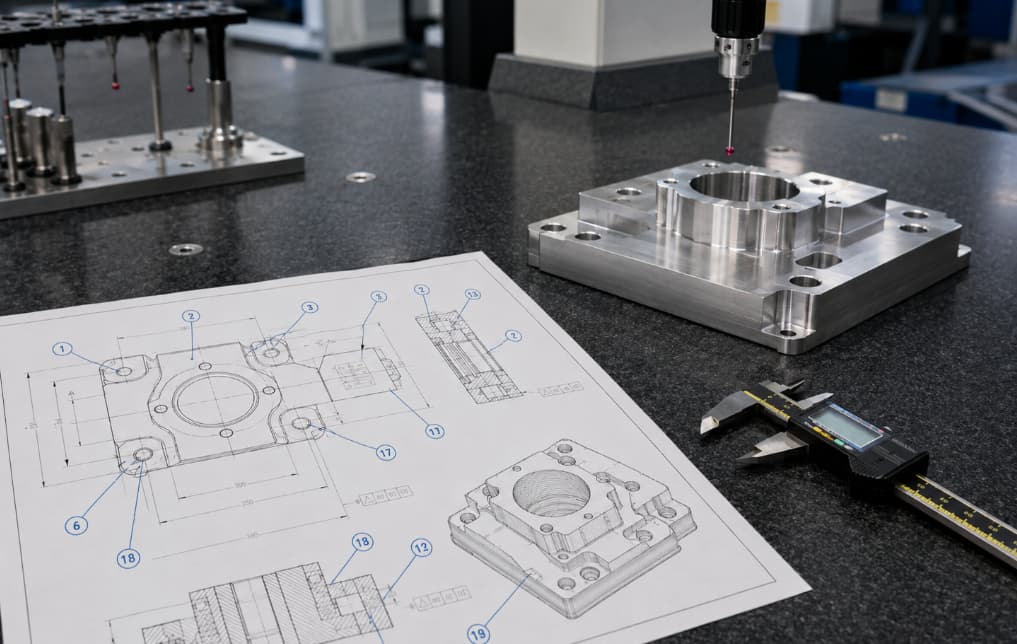
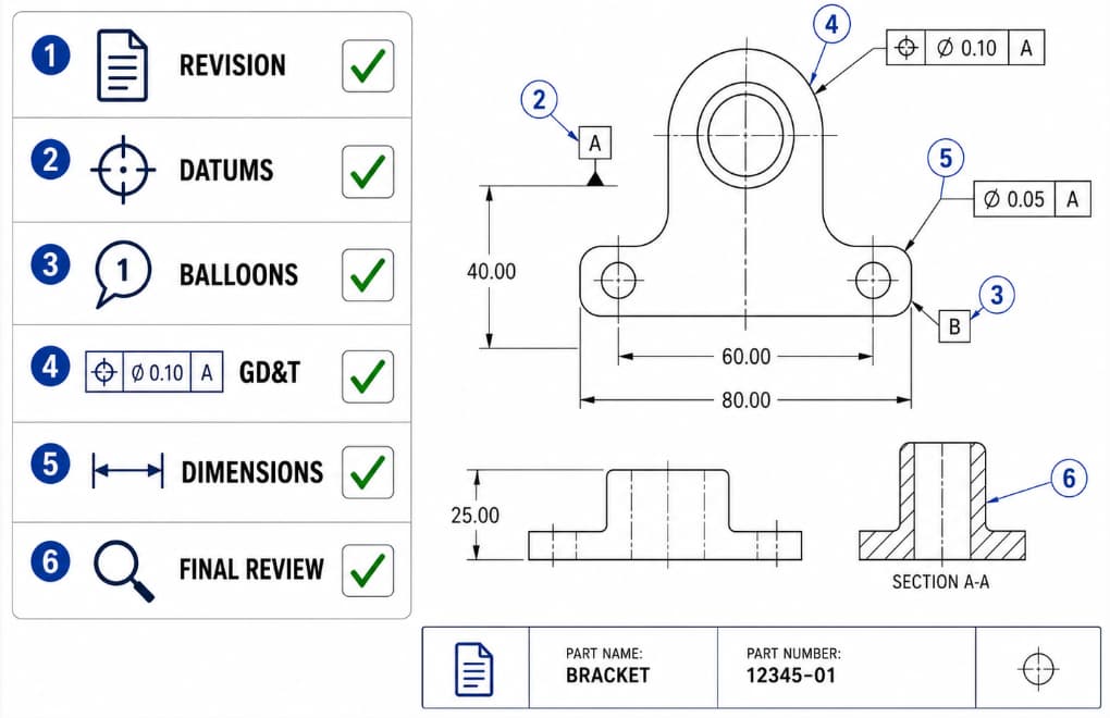
A balloon drawing is a controlled engineering drawing marked with sequentially numbered circles or “balloons”. Each balloon points to a specific characteristic that requires inspection, such as a dimension, tolerance, GD&T callout, material specification, surface finish or drawing note.
The balloon number links directly to the corresponding inspection result, often recorded in AS9102 Form 3 for First Article Inspection. This creates a clear trail from the engineering requirement to the measured result.
Balloon drawings help manufacturers:
- Ensure all inspectable characteristics are reviewed.
- Reduce ambiguity about what must be measured.
- Create traceable links between drawings and inspection records.
- Standardise inspection processes across teams.
- Support audits, customer approvals and quality documentation.
What Makes a Balloon Drawing Effective?
An effective balloon drawing should be clear, readable and easy for inspectors to follow.
| Element | Convention | Purpose |
| Balloon shape | Circular or oval | Makes each characteristic easy to identify |
| Balloon number | Sequential number starting at 1 | Gives each requirement a unique reference |
| Leader lines | Clear, direct lines | Prevents confusion about the intended feature |
| Placement | Outside the part outline where possible | Keeps dimensions and notes visible |
| Grouping | Separate balloons for separate requirements | Supports individual inspection accountability |
Each balloon should point to one measurable requirement. When a feature includes multiple requirements, such as a threaded hole with a depth, diameter and positional tolerance, each applicable requirement should be addressed clearly in the inspection record.
How Do You Create a Balloon Drawing?
Step 1: Verify the Drawing Revision
Before ballooning begins, confirm that the engineering drawing is the correct revision. The revision should match the purchase order, customer requirements and applicable First Article Inspection documentation.
Check that:
- The drawing revision is current.
- All dimensions, notes and GD&T callouts are legible.
- The file format is suitable for manual or digital ballooning.
- Customer-specific inspection requirements have been reviewed.
Using the wrong revision can cause significant quality and compliance issues, particularly when a design change affects form, fit or function.
Step 2: Number Characteristics Systematically
Balloon numbers should follow a logical inspection sequence. Many teams number features in the order an inspector will measure them across the part.
| Balloon range | Feature category | Purpose |
| 1–20 | Overall dimensions and datums | Establishes the inspection reference framework |
| 21–50 | Linear dimensions | Covers lengths, widths, heights and depths |
| 51–70 | Diameters and radii | Groups circular and cylindrical features |
| 71–90 | GD&T callouts | Identifies geometric controls |
| 91–99 | Surface finishes and notes | Captures secondary drawing requirements |
A logical sequence makes the inspection process more efficient and reduces the risk of missed characteristics.
Step 3: Address Complex Drawing Scenarios
Multi-View Drawings
For drawings with front, top, side and section views, each characteristic should receive one balloon number, even if the feature appears in more than one view. This avoids duplicate measurement records.
Assembly Drawings
Assembly drawings may require separate balloon sequences for components and assembly-level requirements. These can include torque values, interface dimensions, fastener specifications and fit requirements.
Model-Based Definition
In model-based definition environments, inspection characteristics may be attached directly to 3D CAD geometry rather than a conventional 2D drawing. These semantic annotations still need to provide clear traceability between the design requirement, inspection method and measurement result.
What Is GD&T?
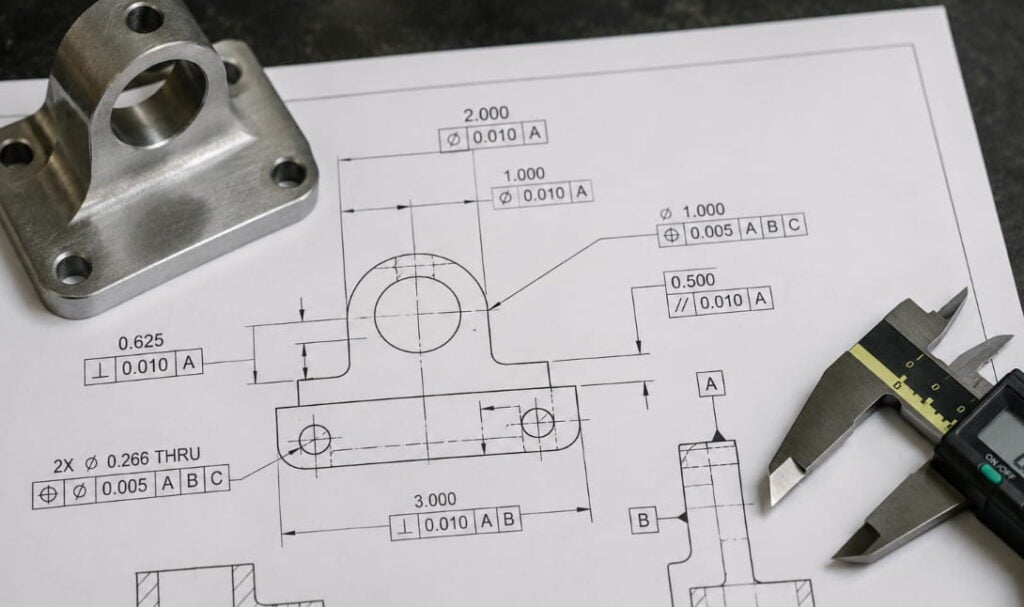
Geometric Dimensioning and Tolerancing (GD&T) is a standardised engineering language used to define how a component’s features must be manufactured and inspected. Rather than specifying only basic sizes, GD&T uses recognised symbols, tolerance values and datum references to control requirements such as position, flatness, perpendicularity, parallelism and runout. This gives manufacturers and quality teams a clearer understanding of design intent, helping ensure parts fit, function and assemble correctly while allowing controlled production variation.
For parts produced through processes such as precision CNC machining, GD&T helps ensure that critical features are inspected according to functional requirements rather than only basic dimensional limits.
How Is GD&T Used in First Article Inspection?
GD&T is particularly important during First Article Inspection because it defines how geometric characteristics must be verified. A standard dimension may state the size of a feature, but GD&T explains how that feature must relate to surrounding surfaces, axes or datum references.
GD&T can define:
- The geometric requirement being controlled.
- The allowable variation.
- The datum reference frame required for measurement.
- The material condition modifier affecting inspection setup.
- The relationship between multiple features.
Understanding these controls is essential because one Feature Control Frame may create several separate inspection requirements.
How Should Feature Control Frames Be Ballooned?
A Feature Control Frame, or FCF, is the rectangular GD&T box that defines a geometric requirement. It may include a geometric symbol, tolerance value, material condition modifier and datum references.
| FCF component | Inspection implication | Ballooning approach |
| Geometric characteristic symbol | Defines what must be measured | Balloon the geometric requirement clearly |
| Tolerance value | Defines allowed variation | Record the complete tolerance |
| Material condition modifier | May affect gaging and setup | Include the modifier in the inspection record |
| Datum references | Establish measurement orientation | Verify relevant datum features separately |
Each distinct requirement should be traceable. For example, a positional tolerance for a hole may require inspection of the hole diameter, the location of the hole relative to datums and the condition of the datum features themselves.
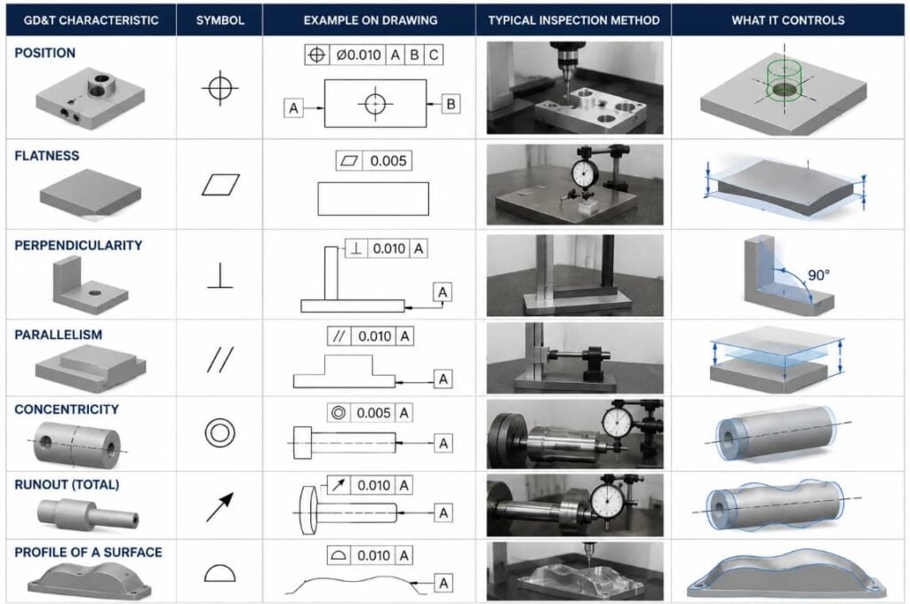
What GD&T Characteristics Commonly Appear in FAI?
| GD&T characteristic | Typical inspection method | FAI consideration |
| Position | CMM or functional gage | Review datum references and material condition |
| Flatness | Surface plate and indicator | Measured without a datum reference |
| Perpendicularity | CMM, square or indicator | Establish the datum first |
| Concentricity | CMM or specialised measurement method | Often confused with runout |
| Profile of a surface | CMM or contour gage | May control complex surface form |
| Runout | Rotational fixture and indicator | Controls form and location together |
| Parallelism | Surface plate and height gage | Requires a datum reference |
| Circular runout | Rotational inspection | Controls individual circular sections |
| Total runout | Rotational inspection with axial measurement | Controls variation across the complete surface |
The appropriate method depends on the required tolerance, part geometry, available equipment and customer requirements.
How Can Digital Ballooning Software Improve FAI?
Digital ballooning software can make the FAI process more efficient by helping teams identify dimensions, apply balloon numbers and generate inspection documentation.
Common digital ballooning features include:
- PDF, TIFF and CAD drawing import.
- Automated dimension and GD&T recognition.
- Balloon numbering and placement tools.
- Revision comparison.
- AS9102 Form 3 export support.
- CMM data integration.
- Collaborative drawing review.
Digital tools are especially useful when managing complex drawings, recurring part families or design revisions. However, software should support engineering judgement rather than replace it. Review is still necessary to ensure every characteristic is correctly identified and linked.
How Do Balloon Drawings Connect to AS9102 Form 3?
Every balloon number on the drawing should correspond directly to a characteristic entry in AS9102 Form 3. This allows an auditor, customer or quality engineer to trace a measured value back to the exact drawing requirement.
| Balloon drawing element | Form 3 requirement | Key consideration |
| Balloon number | Characteristic number | Must match exactly |
| Dimension or callout | Requirement | Record the full specification and tolerance |
| Actual measurement | Inspection result | Record the actual value, not only pass or fail |
| Inspection equipment | Measurement method | Use clear, specific equipment references |
| Acceptance status | Conformance result | Support results with objective evidence |
For more context on whether a complete or limited FAI is required after a change, see our guide to partial vs full First Article Inspection for aerospace suppliers.
How Should Complex Characteristics Be Documented?
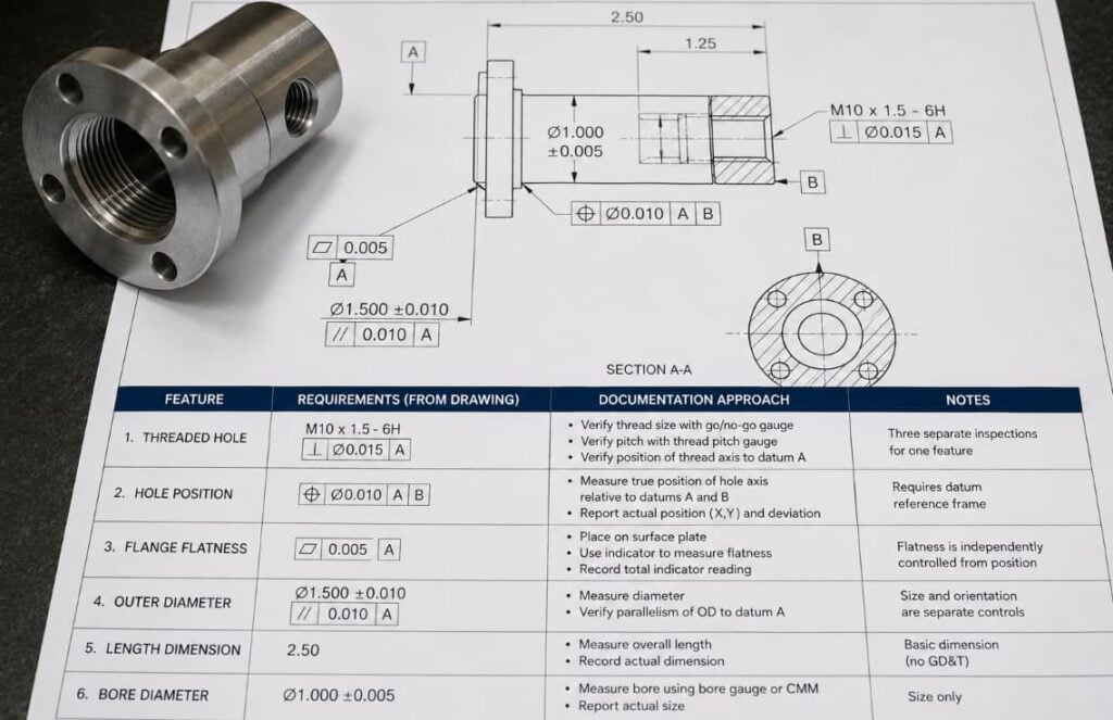
Some balloons represent requirements that need multiple measurements. A threaded hole with positional control, for example, may include:
- Thread size and pitch.
- Thread depth.
- Hole depth.
- Countersink specification.
- Positional tolerance relative to datums.
In these cases, the FAI documentation may require several Form 3 entries connected to one balloon number, or a detailed requirement description that captures every applicable condition.
The main goal is to ensure nothing is missed and every recorded measurement can be traced back to the drawing.
How Are SPC Characteristics Handled in Balloon Drawings?
Some critical characteristics may require Statistical Process Control, or SPC, in addition to First Article Inspection. These features may be marked with special symbols or notes to indicate sampling, criticality or control-plan requirements.
| Balloon notation | Meaning | Documentation approach |
| 15* | SPC characteristic | Reference the relevant control plan |
| 15 (n=5) | Sample size of five | Include sampling requirements |
| 15 Ⓢ | Safety-critical characteristic | Highlight acceptance criteria |
| 15 Ⓒ | Critical characteristic | Apply additional control measures |
SPC requirements should be reviewed early because they may affect inspection frequency, data collection methods and production control plans.
How Should Family-of-Parts Drawings Be Ballooned?
When one drawing applies to multiple related part numbers, the ballooning process should remain consistent while clearly identifying which characteristics apply to each variation.
- Create a matrix showing which requirements apply to each part number.
- Balloon all relevant characteristics.
- Mark non-applicable characteristics as “N/A” where required.
- Maintain traceability between the part number, drawing revision and FAI record.
This approach is particularly useful for similar machined, cast or fabricated components where the main geometry remains consistent but selected features vary.
How Should Supplier-Provided Characteristics Be Managed?
When suppliers provide sub-components with their own FAI documentation, their ballooned drawings and inspection records should be retained as supporting evidence.
Manufacturers should:
- Reference supplier balloon numbers where appropriate.
- Include supplier FAI documentation in the complete inspection package.
- Maintain lot, batch or serial number traceability.
- Verify supplier documentation during incoming inspection.
- Confirm that supplier documents match the correct drawing revision.
Strong document control is essential when managing multiple suppliers or manufacturing locations. Our guide to manufacturing documentation control and material traceability provides further guidance on managing inspection records, revisions and supplier documentation.
How Do You Check a Balloon Drawing Before Submission?
Before submitting a ballooned drawing with an FAI package, verify that:
- The drawing revision matches the purchase order and customer requirements.
- Every required dimension, tolerance, note and GD&T callout is ballooned.
- Reference dimensions are excluded unless specifically required.
- Balloon numbers are sequential and unique.
- Leader lines clearly identify the correct characteristic.
- GD&T callouts and datum features are fully addressed.
- No balloons overlap or obscure important drawing information.
- Title block information remains visible.
- The drawing is stored within the required document-control system.
What Are the Most Common Balloon Drawing Errors?
| Error type | Example | Prevention |
| Missing characteristics | Surface-finish requirement not ballooned | Use a systematic scan pattern |
| Duplicate numbering | Two balloons labelled “15” | Use validation tools or a manual checklist |
| Ambiguous leaders | Leader line crosses several dimensions | Use direct and clear placement |
| Wrong revision | Ballooning Rev B instead of Rev C | Verify revision before starting |
| Reference dimensions included | Ballooning values in parentheses | Understand drawing conventions first |
Conclusion: Why Do Balloon Drawings Matter in FAI?
Balloon drawings and GD&T provide the visual language that turns engineering requirements into measurable quality actions. During First Article Inspection, they help ensure that every relevant feature is identified, measured, documented and traceable.
As manufacturing increasingly uses digital models, CMM data and automated reporting tools, the principles remain the same: clear requirements, accurate measurement and dependable traceability. Whether a part is made through machining, fabrication or casting, a well-prepared balloon drawing helps connect design intent with manufacturing reality.
At Align Manufacturing, we support customers with quality-focused sourcing, engineering and production management across Southeast Asia. From precision machined components to gravity casting Vietnam programmes, we help ensure drawings, inspection requirements and manufacturing processes remain aligned from initial sample approval through repeat production. For teams evaluating sourcing options, our guide to why Vietnam is a hidden gem for gravity casting explains how production capability and quality planning can work together.
FAQ: Balloon Drawings and GD&T for FAI
What is the difference between a ballooned drawing and an inspection drawing?
A ballooned drawing is specifically used to identify and trace FAI characteristics, often linking each balloon number to AS9102 Form 3. An inspection drawing is a broader term for any drawing used during inspection. All ballooned drawings are inspection drawings, but not all inspection drawings are ballooned for FAI.
Should reference dimensions be ballooned?
Usually, no. Reference dimensions, commonly shown in parentheses, are for information only and do not normally require verification. Ballooning them can create unnecessary inspection work unless the customer specifically requests it.
How should repeated identical features be ballooned?
For repeated features, such as eight identical holes, manufacturers may balloon the requirement once and note “8X”, or assign separate balloon numbers to each feature. Customer requirements and the inspection plan should determine the preferred approach.
What software can create balloon drawings from CAD models?
Several tools support digital ballooning, including InspectionXpert, 1Factory, Discus, Balloonist and BalloonX. The best option depends on CAD compatibility, reporting needs and whether integrations with CMM, ERP or quality systems are required.
How should composite position tolerances be ballooned?
Composite position tolerances require careful interpretation because the upper and lower segments control different geometric relationships. Each segment should be evaluated independently, and separate inspection records may be required where the requirements differ.
What balloon numbering convention works best for assemblies?
Common approaches include sequential numbering across the full assembly or separate number ranges for each component. The key requirement is consistency and clear traceability to the bill of materials and inspection record.
How do model-based definition systems affect ballooning?
In model-based definition systems, semantic annotations can be connected directly to CAD geometry rather than placed as graphical balloons on a 2D drawing. These annotations can still provide the characteristic identification and traceability needed for inspection.
Can a supplier’s balloon drawing be modified for internal FAI use?
Supplier documentation should normally be retained as supporting evidence. Manufacturers should create their own ballooned drawing from the applicable manufacturing drawing to maintain document control and traceability.
How should metric and imperial units be handled?
Use the primary units specified on the drawing and record measured values consistently. Where conversions are necessary, document them clearly in the inspection records to avoid confusion.
How do engineering change orders affect ballooned drawings?
When an engineering change order updates a drawing, the ballooned drawing must be revised to match the latest revision. For delta FAIs, only changed characteristics may need reinspection, but the documentation must clearly identify the updated drawing and affected features.